A squarewave of approximately 50:50 duty cycle fed to a bridge rectifier has to produce a DC voltage equal to the peak of the AC. Its got to ")
The diodes can't drop more than around 0.7v. I would recheck the scope readings on that. Make sure the scope is DC coupled and calibrated correctly. If its a dual trace scope then overlay the AC from the tranny onto the rectified DC.
The diodes can't drop more than around 0.7v. I would recheck the scope readings on that. Make sure the scope is DC coupled and calibrated correctly. If its a dual trace scope then overlay the AC from the tranny onto the rectified DC.
Got second probe for my tectronix 3032. Scoped 110v unit secondary winding with Scope internal measurement system:
1. full secondary winding amplitude = 200v.
2. secondary winding center tap to either end amplitude = 100v.
3. ground (aka center tap) to rectified output = 48V DC
so, rectified output is twice lower then its feedstock square wave. Voila.
However, I suspect this is not a problem for 220V unit since the Scope measured 240V amplitude. Previously I measured secondary winding AC with my 20$ uni-T multimeter, which seems can't measure square wave correctly. If the Scope measurement is right, the problem of the 220V unit is 50V higher amplitude on the secondary winding. Unfortunately do not understand how to measure primary winding or regulator - it's negative rail is giving -100V against the Scope's ground...
Attachments
so, rectified output is twice lower then its feedstock square wave. Voila.
Voila
Nah, I'm not buying that
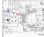
So with the probe ground where the black arrow is, Ch1 where the red arrow is and Ch2 where the blue arrow is you are saying you have lost 50 volts or so across the diode ?
Attachments
Voila
Nah, I'm not buying that
So with the probe ground where the black arrow is, Ch1 where the red arrow is and Ch2 where the blue arrow is you are saying you have lost 50 volts or so across the diode ?
yep, and numbers on schematic say the same: 180V amplitude with +/-45V rectified output. Magic.
The chokes won't make that much difference. Your still not going to lose more than around 0.7 volts across those diodes (not in a forward direction). If the peak of the squarewave applied to the bridge is 100 volts then you must see 100 on the bridge output.
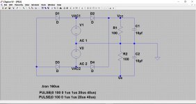
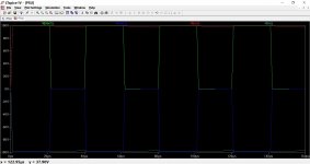
It even simulates correctly. The output voltage on each rail equals the applied peak of the squarewave. Something is amiss with either the measurement or the interpretation of them. VAC1 goes up by 100 volts (from ground) and VAC2 goes down by 100 volts from ground. That gives a -/+100 volt rail as expected. I've made the cap small so you can see the ripple.
It even simulates correctly. The output voltage on each rail equals the applied peak of the squarewave. Something is amiss with either the measurement or the interpretation of them. VAC1 goes up by 100 volts (from ground) and VAC2 goes down by 100 volts from ground. That gives a -/+100 volt rail as expected. I've made the cap small so you can see the ripple.
Attachments
Well its interesting because what you are saying you can measure and see on the scope isn't agreeing with the basic theory
I wouldn't give up at that point, try and understand and find a reason why.
The manual agrees with your measurement... yes... but that still doesn't make sense. It shows a 100 volt peak to peak (there is a centre line running through both illustrations) which suggests it swings 50 volts above and 50 below ground. That would give a -/+50 volt rail.
The 180 part makes no sense at all. That would give -/+90 volt rails.
Look at just D608 and D609. When the anode of each goes to whatever the peak voltage of the secondary is, the cathode must follow. That voltage becomes the positive rail. If it doesn't then voltage is lost across the diode. The negative rail works in the same way but with reversed polarity of the AC waveform and diodes.
Lets go with the crazy idea that that is what is actually happening (it can't be but follow this through).
If the diode were dropping significant voltage then the simple laws of power dissipation (watt = I*V) comes into play. At high current and with any kind of voltage across the diodes then things in the bridge would be heating up... and of course that doesn't happen.
So its a bit of a puzzle that could be interesting to get to the bottom of.
yes, that's interesting portion of theory and nice puzzle, which however does not relate to my primary goal. My current focus still to make it work with 220v mains. 220V unit measured with the Scope now works as follows:
1. PSU input voltage is 140V DC.
2. This is because of voltage drop at 75W "safety" bulb connected in series with AC mains.
3. Secondary winding measures 240V peak to peak, with 35W load bulb.
4. Without invertor running (L604 left leg de-soldered) PSU input is 310V and voltage reg output is 230V, which seems normal.
5. With invertor running, apparently it has over 600V square wave amplitude on primary winding and this is the most concern I have now.
So the first thing I need is to understand how to lower the amplitude at the primary winding. And the thing is definitely not oscillating at the harmonic frequency. I played with C612 - somehow it's affecting the frequency, but only for first seconds, then it stabilized as always - about 52us.
The primary voltages could well be very high but of more concern is the fact that everything on the primary side is live... there is no mains isolation there and what is marked as the zero volt line (ground... but its not) is actually at half mains potential. Its very important you understand that. You can't be connecting grounded test gear to any point on the primary side.
You also can't measure anything on the primary side by using the main audio ground (secondary side) as a reference point. That doesn't work.
With all these high voltages the expected result would be that the secondary side reservoir caps would go pop instantly but I assume nothing like that is happening.
Hi Mooly. Trust you're OK. Simple question:
- having 250v rail voltage in 220V PSU (Voltage reg output) and voltage drop of 120V across emitter-collector on four invertor transistors
VERSUS
- 127v rail voltage in 110V PSU with voltage drop of 65V across invertor transistors,
HOW its make the same amplitude on secondary winding? Because apparently amplitude on primary winding is different, at least two times. What you think?
Its not a simple question and I can't come up with any conclusive answers I'm afraid. All I can do is ask questions...
Is the switching transformer shown as having the same part number in the manual for both versions UK 240vac and the US 120Vac ?
There are a lot of component differences in the two regulators between the two versions. I agree that one is shown as having twice the apparent voltages of the other.
and I can't come up with any conclusive answers I'm afraid. All I can do is ask questions...Is the switching transformer shown as having the same part number in the manual for both versions UK 240vac and the US 120Vac ?
There are a lot of component differences in the two regulators between the two versions. I agree that one is shown as having twice the apparent voltages of the other.
I wonder.
The TA-F6 has different transformers as I recall. This is something only you can get to the bottom of really. I suppose the next step would be some basic testing and comparing of the transformers. Winding resistance is a start and also applying a known test voltage (low level AC from a generator) to see if any differences in turns ratio showed up between the windings.
The TA-F6 has different transformers as I recall. This is something only you can get to the bottom of really. I suppose the next step would be some basic testing and comparing of the transformers. Winding resistance is a start and also applying a known test voltage (low level AC from a generator) to see if any differences in turns ratio showed up between the windings.
I wonder.
The TA-F6 has different transformers as I recall. This is something only you can get to the bottom of really. I suppose the next step would be some basic testing and comparing of the transformers. Winding resistance is a start and also applying a known test voltage (low level AC from a generator) to see if any differences in turns ratio showed up between the windings.
yep, have the same thought. Have to get original working 220V unit...
OK, finally I made it. Transformer is an issue. Just added 25 turns to primary winding and all went as it should, all voltages intact. However, still not checked under 200W load (as per factory set). Found some tricky things, like resistor precision range: 5% resistors are not good - at least in comparator (error amp) the values should be measured manually and selected. Frequency also deviates a bit.
- Home
- Amplifiers
- Solid State
- Sony TA-F6B PSU repair