Does TIP50 come in different hFE ranks?
Sony makes a big deal of the hFE rank in the service manual.
On page 31 it says Q601 and Q613 (regulator) must be "R" rank only
Q609-612 can be either "R" or "O" rank (all four must be same rank)
Reading ilimzn's post here http://www.diyaudio.com/forums/solid-state/181121-sony-ta-f6b-psu-repair-11.html#post2442171 I won't pretend I understand all of it, but correct me if I'm wrong, the regulator is only linear in the starting moment, then it enters some kind of switching mode?
Wouldn't that make the regulator transistors just as, if not more critical than the four switching transistors? and explain why Sony demand "R" rank only, in the regulator?
Google wasn't my friend for finding amc184's FSC2335 but did point me to this:
KSC2335 Semiconductors | Mouser
Looking at the datasheet http://www.mouser.com/ds/2/149/KSC2335-88497.pdf they do have 3 different hFE ranks, "R", "O" and "Y". I know Fairchild isn't Sanken, but if (I know it's a big if) Sanken and Fairchild uses the same hFE classification, the original 2023R's would be the lowest hFE.
Maybe amc184 can confirm if you indeed meant FSC2335 or it is KSC2335, and if your 2335's has a hFE rank?
Testing the original 2023R's hFE sounds like a good idea, but I have no clue as how to do it, other than the meter and the Leader LTC-906A tester I have.
I've just had another look at the circuit and my old reply to ilimzn which I'm not entirely happy with in retrospect.
Lets look at the circuit, and one component in there shows that the regulator (the series pass section of Q601/613) is linear at all times and that component is C604. You could not develop an AC (as in a switching signal) across the cap. It is the voltage across that cap that feeds the pass transistors.
The front end of the regulator operates in linear mode with the DC voltage pot setting the "feedback" to Q605/606. A standard DC regulator. When the switching PSU is running that steady state DC feedback is "modified" according to the load on the PSU which enables the output of the linear reg to increase in order to maintain the rail voltage in the amp under high load. In other words, when the rails in the amp are loaded, the linear reg increases its output to the switching section to maintain the rail voltage. The small auxiliary windings allow for this load sensing (its not perfect because it senses indirectly but it works well enough) At all times the series pass transistors operate in linear mode. D601 that I called a flyback or flywheel diode isn't really in the true sense of the word, it simple clamps any negative going transients that could upset the operation of the regulator.
The hfe rank could be more a matter of ensuring matched devices are fitted here. As I mentioned earlier, there are no current sharing resistors (normally a low value resistor in the emitter) and so unmatched devices would lead to one transistor doing all the work.
I've just had another look at the circuit and my old reply to ilimzn which I'm not entirely happy with in retrospect.
Lets look at the circuit, and one component in there shows that the regulator (the series pass section of Q601/613) is linear at all times and that component is C604. You could not develop an AC (as in a switching signal) across the cap. It is the voltage across that cap that feeds the pass transistors.
The front end of the regulator operates in linear mode with the DC voltage pot setting the "feedback" to Q605/606. A standard DC regulator. When the switching PSU is running that steady state DC feedback is "modified" according to the load on the PSU which enables the output of the linear reg to increase in order to maintain the rail voltage in the amp under high load. In other words, when the rails in the amp are loaded, the linear reg increases its output to the switching section to maintain the rail voltage. The small auxiliary windings allow for this load sensing (its not perfect because it senses indirectly but it works well enough) At all times the series pass transistors operate in linear mode. D601 that I called a flyback or flywheel diode isn't really in the true sense of the word, it simple clamps any negative going transients that could upset the operation of the regulator.
Thanks for the explanation
")
What I don't understand is:
1) how can those two relative small transistors carry so mush current, I mean the amp i rated for 2x100W and consumes up to 550W, all that power have to go thru those two transistors rated for max. 40W each?
2) Why bother whit the switching section at all? just make one more regulator for the negative rail. (setting aside the galvanic isolation issue)
I understand that, but it doesn't explain why only "R" rated is accepted, while "O" witch is good enough for the switching section, is not accepted in the regulator.The hfe rank could be more a matter of ensuring matched devices are fitted here. As I mentioned earlier, there are no current sharing resistors (normally a low value resistor in the emitter) and so unmatched devices would lead to one transistor doing all the work.
You mention 2335 here http://www.diyaudio.com/forums/solid-state/181121-sony-ta-f6b-psu-repair-36.html#post2462953 if you still have them, it could be interesting to know the hFE rating and how they measure.
The KSC2335 at mouser is listed in many different versions, KSC2335R and KSC2335RTU, only KSC2335RTU is in stock but what does the TU mean?
At the moment I think 2335R is the best bet, but I'll order some TIP50 too just in case.
Ah... how does all that power go through a small transistor. Well it doesn't Power doesn't go "through" anything, power is developed "across" something. So the power dissipated by those pass transistors is the product of the current passing through them and the voltage across them. 200 watts output... lets keep it simple and use easy numbers and ignore losses and so on... so, 200 watts on 100 volt rails means a current draw of 2 amps. If the switching supply runs on (say) 400 volts DC then only 0.5 amps needs be drawn from the primary supply to deliver the 2 amps on the secondary. That's assuming the switching convertor is 100% efficient where power in equals power out. The power dissipated in those pass transistors is the voltage across them times the current through them. Lets say you had 500 volts on the collectors and 400 on the emitter. That gives a power dissipation of (500-400)*0.5 which is 50 watts. Shared between two devices that's 25 watts each.
A true (as in more modern) PSU would not use a linear reg at all. All the regulation would be done by the switching supply which would run cooler still without the linear part. You can see the power in vs power out work in practice if you monitor the mains current drawn by say a TV and vary the input voltage from 90 to 250 vac. The TV circuitry dissipates a constant power, say 150 watts. As the line voltage falls the mains current increases proportionally to maintain that "power".
Why bother with a switching reg at all
It was new, it showcased the technology and was a selling point. Lightweight too compared to a conventional tranny. To make a linear reg that was stabilised (which this one is) would need large series pass devices and a lot of heatsinking.
I wouldn't like to speculate on Sonys insistence over the hfe rank for the series pass devices. Electrically they just form a super darlington with the other two drivers, the current gains of all three being multiplied together counting the two pass devices as one transistor)
I'll see if I can find any later to measure.
Power doesn't go "through" anything, power is developed "across" something. So the power dissipated by those pass transistors is the product of the current passing through them and the voltage across them. 200 watts output... lets keep it simple and use easy numbers and ignore losses and so on... so, 200 watts on 100 volt rails means a current draw of 2 amps. If the switching supply runs on (say) 400 volts DC then only 0.5 amps needs be drawn from the primary supply to deliver the 2 amps on the secondary. That's assuming the switching convertor is 100% efficient where power in equals power out. The power dissipated in those pass transistors is the voltage across them times the current through them. Lets say you had 500 volts on the collectors and 400 on the emitter. That gives a power dissipation of (500-400)*0.5 which is 50 watts. Shared between two devices that's 25 watts each.A true (as in more modern) PSU would not use a linear reg at all. All the regulation would be done by the switching supply which would run cooler still without the linear part. You can see the power in vs power out work in practice if you monitor the mains current drawn by say a TV and vary the input voltage from 90 to 250 vac. The TV circuitry dissipates a constant power, say 150 watts. As the line voltage falls the mains current increases proportionally to maintain that "power".
Why bother with a switching reg at all
It was new, it showcased the technology and was a selling point. Lightweight too compared to a conventional tranny. To make a linear reg that was stabilised (which this one is) would need large series pass devices and a lot of heatsinking.
I wouldn't like to speculate on Sonys insistence over the hfe rank for the series pass devices. Electrically they just form a super darlington with the other two drivers, the current gains of all three being multiplied together counting the two pass devices as one transistor)
I'll see if I can find any later to measure.
Sorry, I did mean KSC2335. I got R grade ones, which have an hFE range of 20 to 40. Generally colours at the start of the rainbow are lower hFE or IDSS, so the 2SC2023-Rs (or reds) will be lower gain than the -Os or -Ys (oranges and yellows). Looking at the datasheet, a KSC2335-R and a 2SC2023-R should have fairly similar gain, I wish Sanken had included the gain bin numbers in their datasheet, then I wouldn't have to guess.
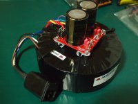
I'm just waiting on the last couple of resistors and a capacitor to arrive to finish rebuilding my PLPS, hopeful I'll be able to test it next weekend. I've also built a temporary linear supply for the amplifier so I'll be able to ramp it up from 0VAC.
I'm just waiting on the last couple of resistors and a capacitor to arrive to finish rebuilding my PLPS, hopeful I'll be able to test it next weekend. I've also built a temporary linear supply for the amplifier so I'll be able to ramp it up from 0VAC.
Attachments
Mooly, thanks for the explanation, now it makes sense, even to me
SMPS or in this case PLPS, at the same time, I hate them, but I'm also fascinated by them, maybe I'll end up loving them lol
When (if) I'm done whit this Sony, I have a SMPS form a Studer mixing console that is blown up, but it looks much more complicated, so maybe not...
amc184, thank you for clearing it up I too wish Sanken had included those numbers in their datasheet.
Did you measure the 2335R's before you installed them, and do you have any surviving 2023R's (or "O") you can measure hFE on?
And where did you buy you 2335R's?
SMPS or in this case PLPS, at the same time, I hate them, but I'm also fascinated by them, maybe I'll end up loving them lol
When (if) I'm done whit this Sony, I have a SMPS form a Studer mixing console that is blown up, but it looks much more complicated, so maybe not...
amc184, thank you for clearing it up
I too wish Sanken had included those numbers in their datasheet.Did you measure the 2335R's before you installed them, and do you have any surviving 2023R's (or "O") you can measure hFE on?
And where did you buy you 2335R's?
Pleased the explanation helped
I've just measured a 2SC2335 and on my meter it shows 35. A BUT11AF reads 25 and an S2000AF (an SMPS/TV Line output type device) reads 5.
For the two pass transistors I really don't see a problem as long as the devices are matched (from the same batch).
I've just measured a 2SC2335 and on my meter it shows 35. A BUT11AF reads 25 and an S2000AF (an SMPS/TV Line output type device) reads 5.
For the two pass transistors I really don't see a problem as long as the devices are matched (from the same batch).
I bought the KSC2335s from Futurlec, where they were listed as 2SC2335s. The 2SC2335-K is equivalent to a KSC2335-Y, the NEC ones were binned M, L, K, while the Fairchild replacements are binned R, O and Y, but the ranges of each bin are the same.
It looks like the digikey listing was for KSC2335-Rs in particular, which is good, those are the best match I think. I'll see if I can match any that I have left.
It looks like the digikey listing was for KSC2335-Rs in particular, which is good, those are the best match I think. I'll see if I can match any that I have left.
Time for a update
I'm pretty sure the 2023's from Dönberg are fakes, the PSU made the familiar high pitch sound, only about 60V output, and after less then a minutte they shorted...
The good news is the KSC2335RTU from mouser works perfectly, no high pitch sound, could easy adjust output to 99V, the speaker relay click in, and the amp plays
Another sign that the 2023's are fake is the hFe, on 15 transistors whit same markings it ranges from 9.5 to 38.
Where as the KFC2335RTU's all 15 transistors measure between 20 and 21.
As for the meter light not working, the bulbs are not original, so the big question is what V and mA should they be?
I'm pretty sure they should be around 6.3V, but some say 250mA others say 70mA.
- Home
- Amplifiers
- Solid State
- Sony TA-F6B PSU repair