Done with my first mod - the MMM - Michael Mardis Mod.
I´m now getting into the second one. This the second one I was thinkting I´ll do like the other drawing - Audio1st first one. Just to see if there is any difference in sound.
Bridged C3 and C4 with wires that I left long enough to connect to the L and R input (the bridging I later on found out was unnecessary, just connect to the right side of the removed C3/4). Did also take away L1 and L2.
After that I got confused. This means that R01, R02, C1 and C2 will be left out of use (according to the T-am schematics) and L1 and L2 are gone. On the Michael Mardis drawing which I followed for my first mod both these two still are in the signal path. I guess the off board R01 and R02 on Audio1st drawing will replace the onboard R01/2 ones.
This must mean something with the C1, C2, L1 and L2 gone ! ! ! ? ? ? ! ! !
Can someone give me a clue, before I go on doing something stupid....
By the way. Removing, bridging etc is a thousand times easier the second time You do it . . . . thanks to Your support and tips.
sonic impact and charlize power
hi guys,
i have both the charlize and sonic impact t-amps in one chassis powered by a single SMPS (5.2 amperes) shared between the 2 amps. the SMPS voltage is set to 13.2v dc. the amps are hooked to a b&w 600i (4 ohm) speaker in a bi-amp connection.
now after trying out each amp separately in normal connection (not bi-amp), i have noticed that the sonic impact produce louder sound than the charlize. but the sound coming from the charlize is more cleaner though. the charlize has with a 3.3uF Clarity cap in the input stage while the sonic impact is stealth modded using 2.2uF Clarity cap.
why would the sonic impact sound louder than the charlize?
is the PSU voltage setting too high for the sonic impact amp and just enough for the charlize that is why the sonic sounds louder?
thanks")
hi guys,
i have both the charlize and sonic impact t-amps in one chassis powered by a single SMPS (5.2 amperes) shared between the 2 amps. the SMPS voltage is set to 13.2v dc. the amps are hooked to a b&w 600i (4 ohm) speaker in a bi-amp connection.
now after trying out each amp separately in normal connection (not bi-amp), i have noticed that the sonic impact produce louder sound than the charlize. but the sound coming from the charlize is more cleaner though. the charlize has with a 3.3uF Clarity cap in the input stage while the sonic impact is stealth modded using 2.2uF Clarity cap.
why would the sonic impact sound louder than the charlize?
is the PSU voltage setting too high for the sonic impact amp and just enough for the charlize that is why the sonic sounds louder?
thanks
Re: sonic impact and charlize power
Hi, The Sonic is set with a higher gain than the Charlize with the input/feedback resistor combination. More gain also means more noise, so that also explains why the Charlize has a cleaner sound.
Lee
weng said:hi guys,
i have both the charlize and sonic impact t-amps in one chassis powered by a single SMPS (5.2 amperes) shared between the 2 amps. the SMPS voltage is set to 13.2v dc. the amps are hooked to a b&w 600i (4 ohm) speaker in a bi-amp connection.
now after trying out each amp separately in normal connection (not bi-amp), i have noticed that the sonic impact produce louder sound than the charlize. but the sound coming from the charlize is more cleaner though. the charlize has with a 3.3uF Clarity cap in the input stage while the sonic impact is stealth modded using 2.2uF Clarity cap.
why would the sonic impact sound louder than the charlize?
is the PSU voltage setting too high for the sonic impact amp and just enough for the charlize that is why the sonic sounds louder?
thanks
Hi, The Sonic is set with a higher gain than the Charlize with the input/feedback resistor combination. More gain also means more noise, so that also explains why the Charlize has a cleaner sound.
Lee
Sharkythefrog said:
This must mean something with the C1, C2, L1 and L2 gone ! ! ! ? ? ? ! ! !
Can someone give me a clue, before I go on doing something stupid....
Doeas anyone any idea?
Can I just go on leaving C1, C2, L1 and L2 out and connect my 2,2 uF input caps (with offboars R01 and R02s to ground) directly to the amp side of the removed C3 and C4?
Or..... sohuld I get some other off board components to replace them?
At the moment, mod two is on hold untill the experienced guys steps into the picture.
Despite the lacy guy I am I red through the thread and found out that L1 and C1 form some sort of a low pass filter (#99) also said to be a said filter(#271) whatever that means.
Low pass filter to stop what - on the input????
If I connect to amp side of exC3 and C4 the thing will wokr as i figure it but I will miss something I guess. Wonder what
I also led that it is the best to connect the new C10 as close to the chip as possible according to remove inductance. What about making a little extra connection on the bottom side of the board at C10 original position to be able to connect two C10s and the +wire from the stiffener caps (will put 3x5600 in tihs mod) on the bottom of the board?????
A newbi on his first own "mission"
Sharkythefrog said:Despite the lacy guy I am I red through the thread and found out that L1 and C1 form some sort of a low pass filter (#99) also said to be a said filter(#271) whatever that means.
Low pass filter to stop what - on the input????
If I connect to amp side of exC3 and C4 the thing will wokr as i figure it but I will miss something I guess. Wonder what
I also led that it is the best to connect the new C10 as close to the chip as possible according to remove inductance. What about making a little extra connection on the bottom side of the board at C10 original position to be able to connect two C10s and the +wire from the stiffener caps (will put 3x5600 in tihs mod) on the bottom of the board?????
A newbi on his first own "mission"
Hi Sharky, sorry for not responding sooner but Sunday is a rest daty afterall
OK so 1st off....yes the caps and inductors crete a low pass filter to remove high frequency RF from the inputs, this makes it easier on the amp.
I have jumped in straight to the pins via an offboard resistor and to be honest I can't tell any difference....is the amp struggling?...no idea!
OK question 2.... look at the link I posted not so far back -extreme modding-, it refers to a thread where '@If' goes into some detail on C10 placement. Personally....I do this modification first before all others because I find it really does make a big difference. I used to drill through the board with a 0.8mm bit and put two caps (one on each VDD pin), that's a little ambitious at this stage so just solder the two + leads between C11 and C12 and the negative leads to the big solder slug.....or just one BIG cap if you can find one?...Just make sure it is very LOW ESR and you're on to a winner

You just have to do what you feel confident with...you know what I mean?
Stay cool man and enjoy the trip, if you loose you're cool
you'll loose your board...and that's damn easy...trust meNo problems Lostcause! I did find something else to do to my three children’s suprise.
OK, RF doesn’t seem to be a big thing on the input (I guessed it had to do something with that) so I just go right in on exC3/C4 then.
This is where You suggest I should connect the two C10s as I Suppose
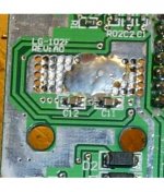
http://www.diyaudio.com/forums/attachment.php?s=&postid=681701&stamp=1121324759
http://www.diyaudio.com/forums/attachment.php?s=&postid=681709&stamp=1121325944
which also would be the bottom one of these two
http://www.diyaudio.com/forums/attachment.php?s=&postid=680706&stamp=1121208887
am I right? Looks as a pretty much possible newbie step. Except from the anxiety of how much film/paint I should scrap away to be sure to get rid of enough of it to have contact and still have anything left of the trace…..
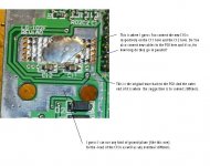
On another post somewhere there was a picture of connecting the incoming +12V directly to the +pole of C10. In this case it would be between C11 and C12. And if I do follow the instruction I should put the stiffener caps between the input +power and input 0power it would be the same as ground. Which leads us to that the stiffener caps and C10 are absolutely in parallel. So why the use of C10 anyway when You have 5 – 15.000uF in parallel with it???? Am I running this the wrong way because I’m missing something or????
When it comes to caps with low ESR I did find a company selling Taiwanese caps with ultra low ESR in various sizes which might due here.
The hottest suggestion would be this I guess. As far as I know my soldering skills I think this has to wait. Far to close to the chip. Maybe on my amp no 10 or so.
http://www.diyaudio.com/forums/attachment.php?s=&postid=680530&stamp=1121191854
http://www.diyaudio.com/forums/attachment.php?s=&postid=680625&stamp=1121201255
Especially as I really didn´t clearly was able to locate all the stuff on the schematics.
http://www.diyaudio.com/forums/attachment.php?s=&postid=680612&stamp=1121199197
If I should only the things I feel confident with I wouldn’t have had any mod at all. I was lucky to have had right ordered the T-amps on the net….. This was about my previous level… But one step after another….
OK, RF doesn’t seem to be a big thing on the input (I guessed it had to do something with that) so I just go right in on exC3/C4 then.
This is where You suggest I should connect the two C10s as I Suppose
http://www.diyaudio.com/forums/attachment.php?s=&postid=681701&stamp=1121324759
http://www.diyaudio.com/forums/attachment.php?s=&postid=681709&stamp=1121325944
which also would be the bottom one of these two
http://www.diyaudio.com/forums/attachment.php?s=&postid=680706&stamp=1121208887
am I right? Looks as a pretty much possible newbie step. Except from the anxiety of how much film/paint I should scrap away to be sure to get rid of enough of it to have contact and still have anything left of the trace…..
On another post somewhere there was a picture of connecting the incoming +12V directly to the +pole of C10. In this case it would be between C11 and C12. And if I do follow the instruction I should put the stiffener caps between the input +power and input 0power it would be the same as ground. Which leads us to that the stiffener caps and C10 are absolutely in parallel. So why the use of C10 anyway when You have 5 – 15.000uF in parallel with it???? Am I running this the wrong way because I’m missing something or????
When it comes to caps with low ESR I did find a company selling Taiwanese caps with ultra low ESR in various sizes which might due here.
The hottest suggestion would be this I guess. As far as I know my soldering skills I think this has to wait. Far to close to the chip. Maybe on my amp no 10 or so.
http://www.diyaudio.com/forums/attachment.php?s=&postid=680530&stamp=1121191854
http://www.diyaudio.com/forums/attachment.php?s=&postid=680625&stamp=1121201255
Especially as I really didn´t clearly was able to locate all the stuff on the schematics.
http://www.diyaudio.com/forums/attachment.php?s=&postid=680612&stamp=1121199197
If I should only the things I feel confident with I wouldn’t have had any mod at all. I was lucky to have had right ordered the T-amps on the net….. This was about my previous level… But one step after another….
Re: sonic impact and charlize power
The Sonic T-amp and the Charlize are 2 totallly different amps! The Sonic T is based on the Tripath TA2024B and the Charlize the Tripath TA2020. The 2024 is rated at 15W @ 4Ù and the 2020 is rated at 20W @ 4Ù. Wattage is absolutley no indication of actual loudness levels however! To do this you need to do some advanced calculus equations to meaure the excact SPL levels taking into effect your speakers effeciency, impendance, etc.
The charlize sound is much cleaner because it uses MUCH higher quality parts than the Sonic-T. In fact the price of the elna caps and the inductors alone on the Charlize cost more than an entire Sonic T does to make!
weng said:hi guys,
i have both the charlize and sonic impact t-amps in one chassis powered by a single SMPS (5.2 amperes) shared between the 2 amps. the SMPS voltage is set to 13.2v dc. the amps are hooked to a b&w 600i (4 ohm) speaker in a bi-amp connection.
now after trying out each amp separately in normal connection (not bi-amp), i have noticed that the sonic impact produce louder sound than the charlize. but the sound coming from the charlize is more cleaner though. the charlize has with a 3.3uF Clarity cap in the input stage while the sonic impact is stealth modded using 2.2uF Clarity cap.
why would the sonic impact sound louder than the charlize?
is the PSU voltage setting too high for the sonic impact amp and just enough for the charlize that is why the sonic sounds louder?
thanks
The Sonic T-amp and the Charlize are 2 totallly different amps! The Sonic T is based on the Tripath TA2024B and the Charlize the Tripath TA2020. The 2024 is rated at 15W @ 4Ù and the 2020 is rated at 20W @ 4Ù. Wattage is absolutley no indication of actual loudness levels however! To do this you need to do some advanced calculus equations to meaure the excact SPL levels taking into effect your speakers effeciency, impendance, etc.
The charlize sound is much cleaner because it uses MUCH higher quality parts than the Sonic-T. In fact the price of the elna caps and the inductors alone on the Charlize cost more than an entire Sonic T does to make!
Lostcause said:
OK question 2.... look at the link I posted not so far back -extreme modding-, it refers to a thread where '@If' goes into some detail on C10 placement. Personally....I do this modification first before all others because I find it really does make a big difference. I used to drill through the board with a 0.8mm bit and put two caps (one on each VDD pin), that's a little ambitious at this stage so just solder the two + leads between C11 and C12 and the negative leads to the big solder slug
Looked at my board and did find something that didn't look like the pictures I related to in my last post. You where talking about drilling holes. When I look at my board it looks like it's two through passes down to the other side of the board right there where I was supposed to solder my +leads from the caps. Wher do they go??? As I haven't found out where C11/12 (as well as the C10) are on the schematic I'm not quite shure of doing the right thing just solder to the whole...
Still wondering about the C10 totally in parallell with the stiffener caps. Why use C10? From my last post up here. No ee that has a great expl?!
Attachments
Hi Sharky, quick answer....I'm just in the middle of something..
You're board is not the standard layout so we will have to look at the traces to be sure....
C10 is to ensure that you have a filter cap as close as possible to the chip... if you put the cap/s under the board then they replace C10 as they are closer... I was refering to C10 as the low esr filter cap rather than the original....no harm in leaving that there though as well....
OK, time to answer you now...
The two through holes are the same on any model of Sonic, they go through to the supply trace under the chip. That's why you should solder them there. The two SMD caps (C11/12) are the other filter caps and are very important.
However, I have been warned about 'oscillation' from two caps in the same position so I drill through from the end of the supply pins (different position) so that each supply only draws from one capacitor....and I can get it slightly closer to the pins.
I also used to cut the trace between the pins on the board so they were totally independant all the way back to the PSU.
Those new boards look better quality and possibly a better design, but be carefull when reading about past references (C10 etc) as they may not be the same between board revisions.
EDIT: On closer inspection your board is only slightly different from the one's posted on most mod sites and throughout this thread.
Lostcause said:
The two through holes are the same on any model of Sonic, they go through to the supply trace under the chip. That's why you should solder them there.
OK! Trying to gain some knowledge here, supply to what according to the schematics I linked to in my second last post?
OK, but same question as above, but where to find them on the schematics, There are no numbers or even sometimes the right size (33uF for C10 etc)Lostcause said:
The two SMD caps (C11/12) are the other filter caps and are very important.
Lostcause said:
However, I have been warned about 'oscillation' from two caps in the same position so I drill through from the end of the supply pins (different position) so that each supply only draws from one capacitor....and I can get it slightly closer to the pins.
I try to understand. I guess You mean the supply pins on the chip, and that's somewhere else. But where does it then connect to the C11/12?
Lostcause said:
I also used to cut the trace between the pins on the board so they were totally independant all the way back to the PSU.
Isn't that the whole thing if have understand anything
which might not be the case. To make a cut between the two holes inside of C11 and C12 because they supply to different parts of the chip (different channels maybe????). Does that mean that You connect one C10 to each hole and also cut the power trace just before reaching C11 and C12 and make new power loads via cables from each one of C11 and C12???Does that also mean that one could connect one Stiffener cap (lets say 5600-10000uF) in parallell with the C10:s respectively?
The last question comes from my present thinking that the stiffeners seems to be in total parallell with C10 as decribed earlier - combining different posts. Or am I wrong here?
Lostcause said:
Those new boards look better quality and possibly a better design, but be carefull when reading about past references (C10 etc) as they may not be the same between board revisions.
EDIT: On closer inspection your board is only slightly different from the one's posted on most mod sites and throughout this thread.
Yes I agree in both cases. Brought up @lf:s and my pictures of the same place of the board on the 19" screen and found out that the where very much the same. Just less solder slug on my new board and som minor changes on the traces.
I still do have a bit of a problem following all Your explanations. But looking at myself now compared to a couple of months ago I would have considered myself as an expert from that time beeing. As the newbie I still in fact am.
Attachments
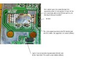
And this is - according to my very very basic knowledge combined with a number of posts along the way of this thread, how it could look like if I try to follow them.....
To complete the picture there should be another one of each thing, but connected to the hole of C12.
To complete the picture there should be another one of each thing, but connected to the hole of C12.
Attachments
Sharkythefrog said:
To complete the picture there should be another one of each thing, but connected to the hole of C12.
Ofcourse with cuts made between the holes inside C11 and C12 and a close to C11/12 cut on the trace back to the power-in pole.
That is if I should try to follow the instructions from Your post Lostcause together with the other ones.
Somewhere it feels like I'm messings things up, but still... following the advices about stiffeners and C10s it could according to my mind look like this. Even if it doesn´t make any sence having both a small low ESR cap and a much bigger ultra low ESR cap in parallell - or does it?????
OK, mod 2 done.
Done and LED light but absolutely no sound.
Started to measure Ohms everywhere and got myselt some very strange result.
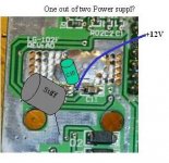
Zero resistans between +power and ground. Measured between the +13V power input connected to C10 and the ground slugs wherever.
Everything on the input side seamed ok, without really knowing what numbers there should be. But with 0 kOhm over the 47k resistor before the 2,2 caps didn't look right so I just took one away and measured it and it was 47k. But well in place again it was 0 again, strange. That means (I think) that I got 0 Ohm between input and ground comming in from the back in some way.
Looked at the board very thoroghly through the magnifying glass and did find that the ground connection pin on one of the stiffeners had contact with the upper side of C12. I corrected the stiffener while the board sat on its position in the case because it didn't really had the position I liked it to have. I soldered it then in a position without seing so it came out connected to C12.
So when a connect the amp up there is a "tick" sound which doesn't exist on the first mod, no music sound what so ever and when I turn the pot up to max there is a razzeling noice, but no sound.
Seems that I might have burnt my first Tripath chip....... ;-) or :-(
Anyone got any Idea of where I could measure on the chip/board to find out if it's gone or not.
Done and LED light but absolutely no sound.
Started to measure Ohms everywhere and got myselt some very strange result.
Zero resistans between +power and ground. Measured between the +13V power input connected to C10 and the ground slugs wherever.
Everything on the input side seamed ok, without really knowing what numbers there should be. But with 0 kOhm over the 47k resistor before the 2,2 caps didn't look right so I just took one away and measured it and it was 47k. But well in place again it was 0 again, strange. That means (I think) that I got 0 Ohm between input and ground comming in from the back in some way.
Looked at the board very thoroghly through the magnifying glass and did find that the ground connection pin on one of the stiffeners had contact with the upper side of C12. I corrected the stiffener while the board sat on its position in the case because it didn't really had the position I liked it to have. I soldered it then in a position without seing so it came out connected to C12.
So when a connect the amp up there is a "tick" sound which doesn't exist on the first mod, no music sound what so ever and when I turn the pot up to max there is a razzeling noice, but no sound.
Seems that I might have burnt my first Tripath chip....... ;-) or :-(
Anyone got any Idea of where I could measure on the chip/board to find out if it's gone or not.
Attachments
When I first finsihed my mods I also had no sound (well jsu tfrom one channel). Turns out the problem was teh circuit board is made so cheaply that the through hole tinning job is very poor. When I soldered from the top & bottom of the board where I connected my wires and caps it fixed the problem! Try the same on your board.
If you're drilling out the holes, you are sure to remove the thru-hole tinning.
In that case it's mandatory to solder both top and bottom side, or if you can't reach one side, to really pour on the heat and try to make sure solder flows up the wire and makes contact with the hidden pad.
--Buckapound
In that case it's mandatory to solder both top and bottom side, or if you can't reach one side, to really pour on the heat and try to make sure solder flows up the wire and makes contact with the hidden pad.
--Buckapound
- Status
- This old topic is closed. If you want to reopen this topic, contact a moderator using the "Report Post" button.
- Home
- Amplifiers
- Class D
- Sonic Impact 5066 Parts List & Modifications