It´s the right channel that does not work.
And by the way. Measuring from the amp side of the input resistor through the cap to the amp side get this result Left: 154k Ohm, Right: no connection - infinity. Nothing even close to the 20k you menthioned. Amp side of the input resistor must be the same as input side of the input cap according to my schgeme and the first Audio1st drawing
Masuring the resistors they are both fine 21,8k.
By the way (again) the only running channel does sound a LOT better even after just less than an hour of playing than from the beginning . Strange!!!
Another diagram that I hope might help somebody out there....
thanks, that will help.
Hi!
I started modding my little T-amp yesterday, changed the connectors on the back.
But I also want to change the input capacitor as I've read the original ones "chokes" the bass. The problem I've encountered is that the revision of the PCB found in all(?) modding-guides found online are from somewhere in 2004, but mine PCB is from the beginning of 2006, and it looks completely different from the ones' that I've seen pictures of..
So, the question is; are there any more recent modding-guide availible? Or is it as simple as the capacitors still has the same names (C3, C4?) as before, even if they're not in the same place?
Great pics Lostcause!
A month or so ago I did try to follow the tracks on the board and compare it with the schematic someone (Motherone???) presented here a +year or so. I gave up as I found myself losing track when they passed through the holes in the boards and seemed to show up somewhere else. How do You do that??
If I figured out this right (without looking at the schematic) I´ll track it from input to L1 and ("inside" or on the other side of the board) to C3 and then to R4 and then into the chip. Right?
It will have to wait for a while - now it´s Tacos for the kids etc etc etc. Maybe a late night work.

What size are C1 and C2? They look like 0603 size. Is this correct? And also im getting mixed answers on what size cap to use on the speaker out binding posts. The picture on michael mardas website says to use a 0.1uf but in an email and on the tripath website they say to use a 0.01uf! Even mike in an email said to use a 0.01uf...why the descrepency here? I measured the cap that came with the amp attached to the speaker posts and it is indeed a 0.1uf capacitor.
Picklgreen!
Me myself don´t have clue at all but for the outtput caps it seems to be 0.10 or 0.15 that is "most popular" on this forum. Woudn´t think that the size is crusual as some drawings describes the output with no caps at all.
I wouldn´t bother with the discrepancy, just use some better ones than the original in the same range of size and I guess you are home free.
C3 it is! ! ! !
0,0 all the way to the bridge at C3. But from the bridge to R1 it´s 1 (infinity) on the mm. So it´s the amp side of the C3 bridge that is not working, the one that i had problems with.
Should I use a sharp knife to scrape on the trace to find something to solder on close to the C3 to make a new bridge, or should I just try to solder a thin wire from the bridge to the input side of R1 (if that is possible to on the SMD)????
picklgreen said:on the tripath website they say to use a 0.01uf! Even mike in an email said to use a 0.01uf...why the descrepency here?
There is definitely confusion here. Even I'm confused.

I searched again thru the Tripath data sheets and ALL but one says 0.01uF. It seems to show up as 0.1 on the TA2021 data sheet - I think it's a mistake.
The AMP6 uses 0.22uF! Some amps have no cap there.
I have tried everything up to 1uF and it didn't seem to bother the amp. Most amps would hate this. The larger the cap, the more it rolls off the top end. 1uF is certainly too big, it cuts into the audio band.
The reason the cap is there is to drain off RFI that would go out the speaker lines.
See an example below of a slightly better filter for a Tripath data sheet. The Fenice 20 uses a filter like this.
Attachments
Still no red led but there is sound YES ! ! !
Took away the C3bridge and managed to scrape on the track close to the C3 so I got the posibility to solder a tiny tiny little piece wire to it and then solder on the side that was ok soldered the prevous time. And then mr Lostcause there where 20k and nothing else as You said, from the amp side of the input cap to the amp side of the input resistor. Thanks for all the help, really appr it ! ! ! !
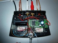
My son Axels Pioneer CDplayer with the 1/4wawe-pipe Voight-horn are now playing with a very stiff and nice base and fairly clear and open mid and high (as much as it is possible get from those speakers). Don´t know about the really low base as the speakers are closing down at 40-50Hz.
So now on to the next amp. My son Oskars T-amp. This time I will try to put parallell 470uF C10:ns (on top and on bottom) and parallell 5600uF as stiffeners to se if there will be any difference. What would I expect guys?
This is it, standing on the CD burning in and waiting for a new blue led, the shell and the new aluminum knob.
Took away the C3bridge and managed to scrape on the track close to the C3 so I got the posibility to solder a tiny tiny little piece wire to it and then solder on the side that was ok soldered the prevous time. And then mr Lostcause there where 20k and nothing else as You said, from the amp side of the input cap to the amp side of the input resistor. Thanks for all the help, really appr it ! ! ! !
My son Axels Pioneer CDplayer with the 1/4wawe-pipe Voight-horn are now playing with a very stiff and nice base and fairly clear and open mid and high (as much as it is possible get from those speakers). Don´t know about the really low base as the speakers are closing down at 40-50Hz.
So now on to the next amp. My son Oskars T-amp. This time I will try to put parallell 470uF C10:ns (on top and on bottom) and parallell 5600uF as stiffeners to se if there will be any difference. What would I expect guys?
This is it, standing on the CD burning in and waiting for a new blue led, the shell and the new aluminum knob.
Attachments
Sharkythefrog said:there is sound YES ! ! !
Thanks for all the help, really appr it ! ! ! !
Hey, no problem mate.
I was once in your position and very much appreciated the help I got from our fellow members


So now on to the next amp
Now you have started on this path my son...... it's never ending!
Welcome to your destiny

After another hour - It´s really amazing how good it is the little thing. Donald Fagens Morph the Cat is absolutely fantastic on that little piece with Axels simple homemade Voight horns connected to it.
It has a much more open, bright and clear picture, with an absolutely vonderful base now after a few hours of playing. It seems to fit the speakers so well, fast and stable all the way down to lowest base. You can really hear where the speakers quit, which I guess is down to 40Hz something when I think of it.
I might give the little thing a try with my Thiel speakers tomorrow to se what that will give. My guess it will alright up to nrmal levels of sound and then problems as they are not very easy driven and the room is about 40 sq mtrs. But we´ll see.....
And by the way. A few days ago I came up with the next project (after finishing Oskars T-amp). I think I will put a modded T-amp inside two or three connected 3 ltrs Vine boxes, preferably Mauro Primitivo who is looking great, with some suitable speakers built in..... Perfect for the beach, the park and/or the boat. . .
Is that so, Lostcause....
Well it´s more healthy and cheaper than a lot of other things I can think of being addicted to - so says my new lady too.....
I did have a hifi interest in my Youth, but it got lost during the path to mid age, crushed by bigger house building projects, kids and other stuff. I still got i huge box filled with tonearms, cables, pickups, lexan turnatable plates, concrete bodies etc etc, and a shelf with cardridges, amps, speakers of all sizes (except for the ones given away, lent to friends children etc).
But this new thing is really great. No jigsaws, no special ordes to a freinds friends friends mechanical factory etc . . . . Just a few components on the kitchen table and a soldering station.... And above that - a number of absolutely great guys willing to help. What could be better!! (I can think of a few things actually, but anyway)


So for now !!!
Well it´s more healthy and cheaper than a lot of other things I can think of being addicted to - so says my new lady too.....
I did have a hifi interest in my Youth, but it got lost during the path to mid age, crushed by bigger house building projects, kids and other stuff. I still got i huge box filled with tonearms, cables, pickups, lexan turnatable plates, concrete bodies etc etc, and a shelf with cardridges, amps, speakers of all sizes (except for the ones given away, lent to friends children etc).
But this new thing is really great. No jigsaws, no special ordes to a freinds friends friends mechanical factory etc . . . . Just a few components on the kitchen table and a soldering station.... And above that - a number of absolutely great guys willing to help. What could be better!! (I can think of a few things actually, but anyway)
So
for now !!!As my previous post said, my PCB looks different to the ones that I find in various guides, so I thought pictures of it maybe will help a bit more.
On "the other side" of the PCB I can read:
Languang
Lgf-005 Rev. D
06-04-10
The top of it:
The other side:
On "the other side" of the PCB I can read:
Languang
Lgf-005 Rev. D
06-04-10
The top of it:
An externally hosted image should be here but it was not working when we last tested it.
The other side:
An externally hosted image should be here but it was not working when we last tested it.
audio1st said:Another diagram that I hope might help somebody out there....
Dear Audio1st,... "first" of all I want really thank you for your
precious pictures/schematics that allowed me, and many others,
to operate in complete safety the t-amp modifications.
Notwithstanding this, am I impudent if demande you the permission
to pubblicate same your pictures in my (not commercial) site?
http://it.geocities.com/silvio_b2002/audio/t-amp/batteria/batteria1.htm
Whichever your answer, I sincerely thank you, very much!
(also I would express my gratitude to any others tread participants
especially to the great Michael Mardis)
Excuse me for my "tribal" English language, a sort of made in Italy diy slang!
Silvio
What is the correct value of capacitor to use on the output posts? 0.1uf or 0.01uf??? noone seems to know the correct aswer here. I am currently using 0.1uf and bypassing the input LCR filter (just using the 20K resistor and 2.2uf cap). I have terrible high freq response. how can i fix this? these amps are supposed to have great high freq response! Im thinking it has to do with my output filter freq cutoff but i dont know what cap values to use to calculate the freq correctly.
I have great bass though...22000uf ps cap and replaced c10 with a panasonic 680uf FC.
If i cant figure out the high freq response problem this thing is going in the trashcan!
I have great bass though...22000uf ps cap and replaced c10 with a panasonic 680uf FC.
If i cant figure out the high freq response problem this thing is going in the trashcan!
Hello Silvio,SilvioBrasini said:
Dear Audio1st,... "first" of all I want really thank you for your
precious pictures/schematics that allowed me, and many others,
to operate in complete safety the t-amp modifications.
Notwithstanding this, am I impudent if demande you the permission
to pubblicate same your pictures in my (not commercial) site?
http://it.geocities.com/silvio_b2002/audio/t-amp/batteria/batteria1.htm
Whichever your answer, I sincerely thank you, very much!
(also I would express my gratitude to any others tread participants
especially to the great Michael Mardis)
Excuse me for my "tribal" English language, a sort of made in Italy diy slang!
Silvio
thank you for your comments and of course you are welcome to use my pictures.
Cheers Barry.
- Status
- This old topic is closed. If you want to reopen this topic, contact a moderator using the "Report Post" button.
- Home
- Amplifiers
- Class D
- Sonic Impact 5066 Parts List & Modifications