I think the correct technical term is to set the film!
When producing the film it has been subject to great preasure and the molecules are "mangled out off positions". In some cases this is a good thing, but as for PET films I belive this is the major cause for the film to start "creeping" after you tension it. When you heat treat the film you get it back to a more stable phase. If you do this before or after tesioning the film is really a choice of taste.
I can see two benefits of doing it before stretching:
1. You do not have to tension the film so hard. (no loss of tension as the
heatreatment is already done) => less stress on glue/spacers
2. The tension you measure when stretching the film is basicly what you end up
with.
Roger
I have had very good results using the heat method and I am now wondering if mechanical stretching is even worth going through from what I have been reading.
The only mechanical stretching that occurs in my process is when I lay the mylar out on a piece of glass to get the wrinkles out.
When do this I first wet the glass with some alcohol (denatured or isopropynol or even water may work) and then I gently rub out all of the air bubbles and wrinkles and then tape the edges to keep the mylar from lifting off of the glass.
At this time I may add a little more tension depending on how bad some of the wrinkles are, as my mylar does have some.
Having the mylar stuck to the glass with some alcohol helps greatly to keep the mylar stable when I drop the sticky glued frame on to it,
It also allows me to make any small adjustment should I miss my mark without it wrinkling much and any wrinkles are usually correctable.
Then I weight down the frame with another piece of glass and wait until the epoxy is just starting to set then I pull off the weights and piece of glass so that it doesn't get stuck to the top piece of glass from the oozed out epoxy.
I takes a few time to get a feel of how much to use,Very little is needed but I use a slow setting type.
I have this procedure down pat so now I can use a 30 min setting type as it actually takes about an hour for it to set anyhow.
Then when it is set I trim it up and mount the frames and then hit with some heat.
The heat usually takes out any wrinkles that can occur.
I have only had one or two that did not come out to my liking, although the diagphram still worked fine, out of all of the times I have done this.
I have gotten very consistent results doing it this way and my resonate frequency of the diagphram in the 70Hz to 90Hz for my little panels and are within +/- 5hz to 10 hz per pair.
Also after taking them apart and putting them back together the tension is the same as well as the resonate frequency of the diagphram and very rarely (only a couple of times) did I have to reheat them one more time.
I also tried heating to see if they would see if they would shrink more but their resonate frequency did not go much farther than about 90Hz.
I have used a model airplane covering once that did keep shrinking and broke the unmounted frame that it was glued to.
I still have some of this material and it is one of the thinnest ones you can get.
My guess is that it is not an't Tensilized PET film.
But once it got to a certain point it had seemed that it wasn't going to shrink anymore.
The frame was all twisted up and it was when I tried to remount it is when it broke as the material absolutely would not stretch enough at all to line up the screw holes and the frame snapped before the film would give way.
That's my experience on Diagphram tensioning.
jer 🙂
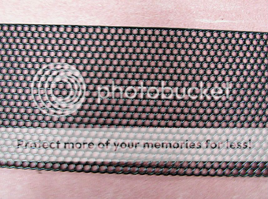
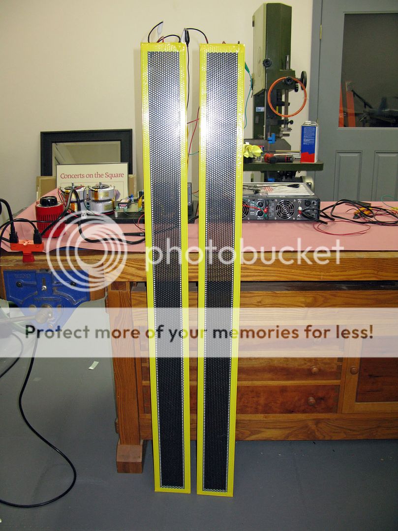
I finished up one mid/tweeter test panel today. Hopefully I will get around to testing it on Sunday. Here is what it came out as:
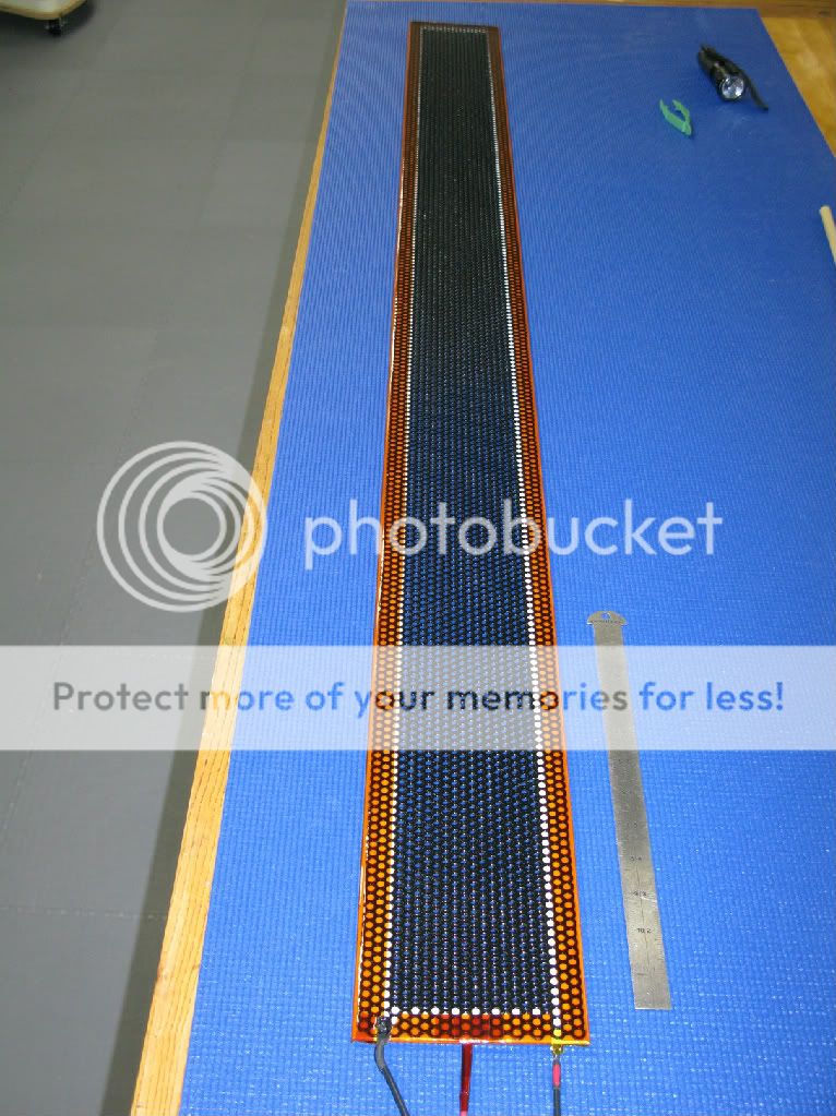
The insulating tape around the perimiter is Kapton.
The insulating tape around the perimiter is Kapton.
Very Nice !!!
Can't wait to see your next report.
I am still tiding up some lose ends around here and then I will get back to testing my old panels to gather some more info on driving voltages.
I wiil also try using a few thicker frames to see how much this will help the low end a bit.
I am pushing for a 200Hz to 250Hz range,as 300hz was about the limit using a D/S of .075" and started to clip below that at high volumes.
Then I will start on the construction of my longer versions.
Great job !!!
jer 🙂
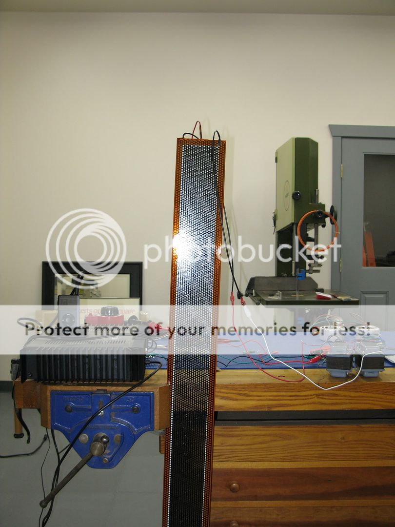
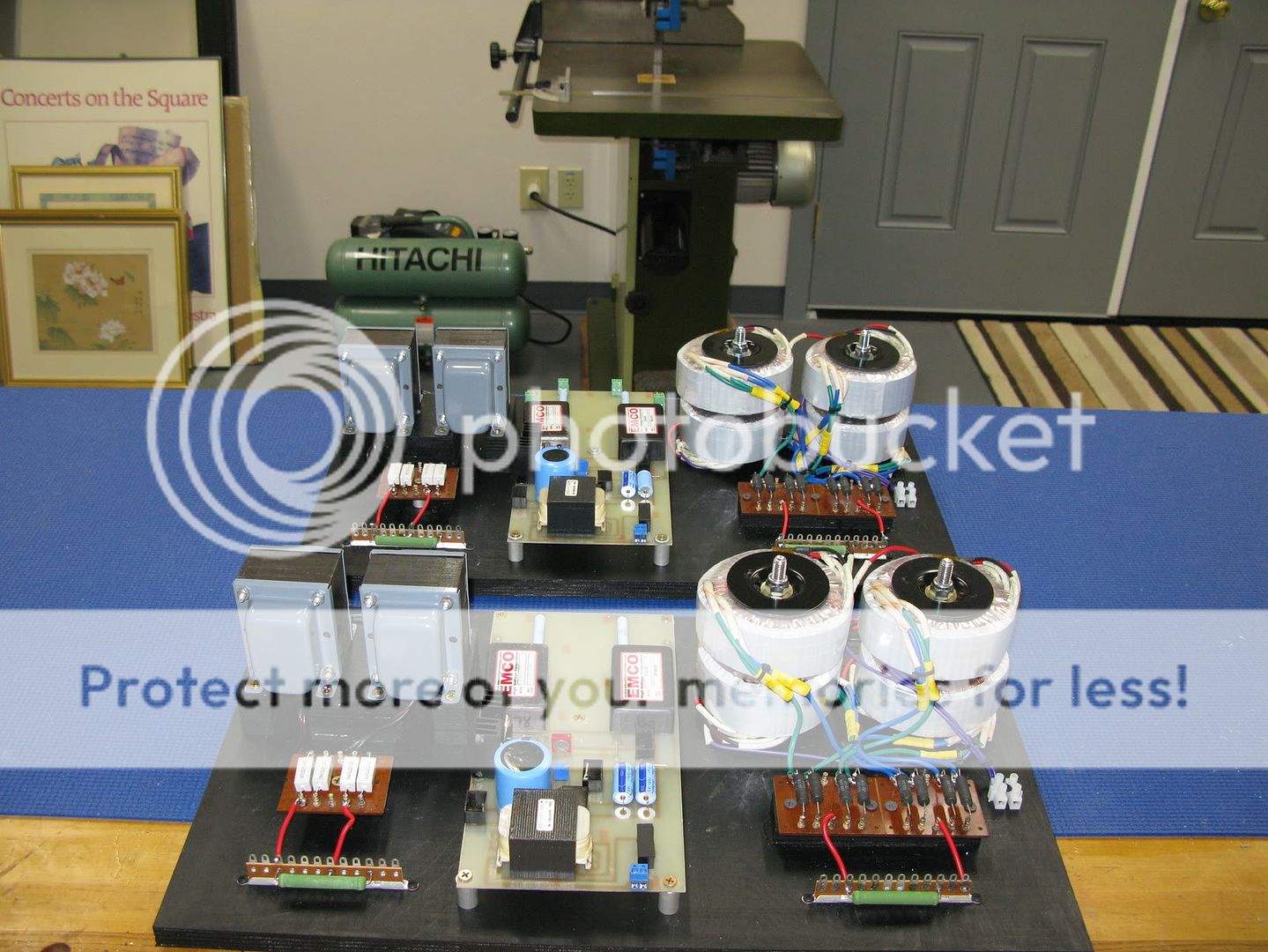
I hooked up my one test mid/high panel last night and ran some music from an ipod through it. With the two transformers shown in the picture below, it sounded great and was louder than I could ever listen at. This panel has .0625 spacing so I think I'll stick with that. I also tried out one of the oil burner transformers on it. Delinitely for the woofer panels only becaust only low frequencies came through it.
Here are some pictures:
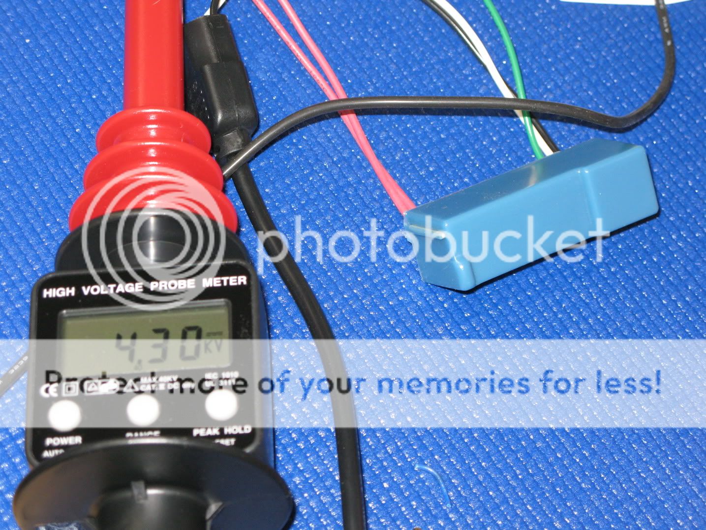
The bias was set at 4.3 KV and no rching. I couldn't set it any higher because any more voltage from the variac caused it to jump to over 6KV whick caused a lot of sizzling.
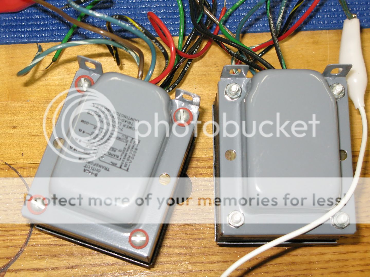
These are the transformers I'll be using. They are left over from the ELS's I built many years ago when Sanders published his first article in The Audio Amateur.
Here are some pictures:
The bias was set at 4.3 KV and no rching. I couldn't set it any higher because any more voltage from the variac caused it to jump to over 6KV whick caused a lot of sizzling.
These are the transformers I'll be using. They are left over from the ELS's I built many years ago when Sanders published his first article in The Audio Amateur.
The bias was set at 4.3 KV and no rching. I couldn't set it any higher because any more voltage from the variac caused it to jump to over 6KV whick caused a lot of sizzling.
This is the way you bias the soundlabs...tell you hear the sizzing an you back off a littel....
I have found that the bias is the tone EQ for the sound of any ESL panel ..Like a EQ... the res. at the end can change the sound... put a diff 10m ohm2w sound well chang.. find the one that sound the best with your panels...i am useing a 10m ohm1/2w on panels above 300hz....3400 bias... sounds live...like your there...put 40m in rolls you way back... you can set the top panel...to the bass panels...50-60m ohms ...well turn the panel down...20m ohm well bring it up a little... this is cool an eze...
Awesome,Very cool !!!
I told you that sucker was going to be loud!!! he,he,he
I couldn't get much over 5.8Kv before some kind of breakdown of the air would start with my .075" gap.
On occasion I would get up to 6.5kv to 7 kv with the supply loaded (maxed) with no load and just the resistor divider to would do 7.5kv.
My new supply is more stout and should do better,But I am sure I won't be able to get any higher until I increase the D/S spacing due to the limits of the air.
I ran them at an optimum level of about 5.5kv all of the higher voltages were just tests to see how far I could push the limits.
I see with the transformers that you are using that you are about a 1:88 transformation ratio with the 4 ohm tap.
Keep up the great work !!!!
jer 🙂
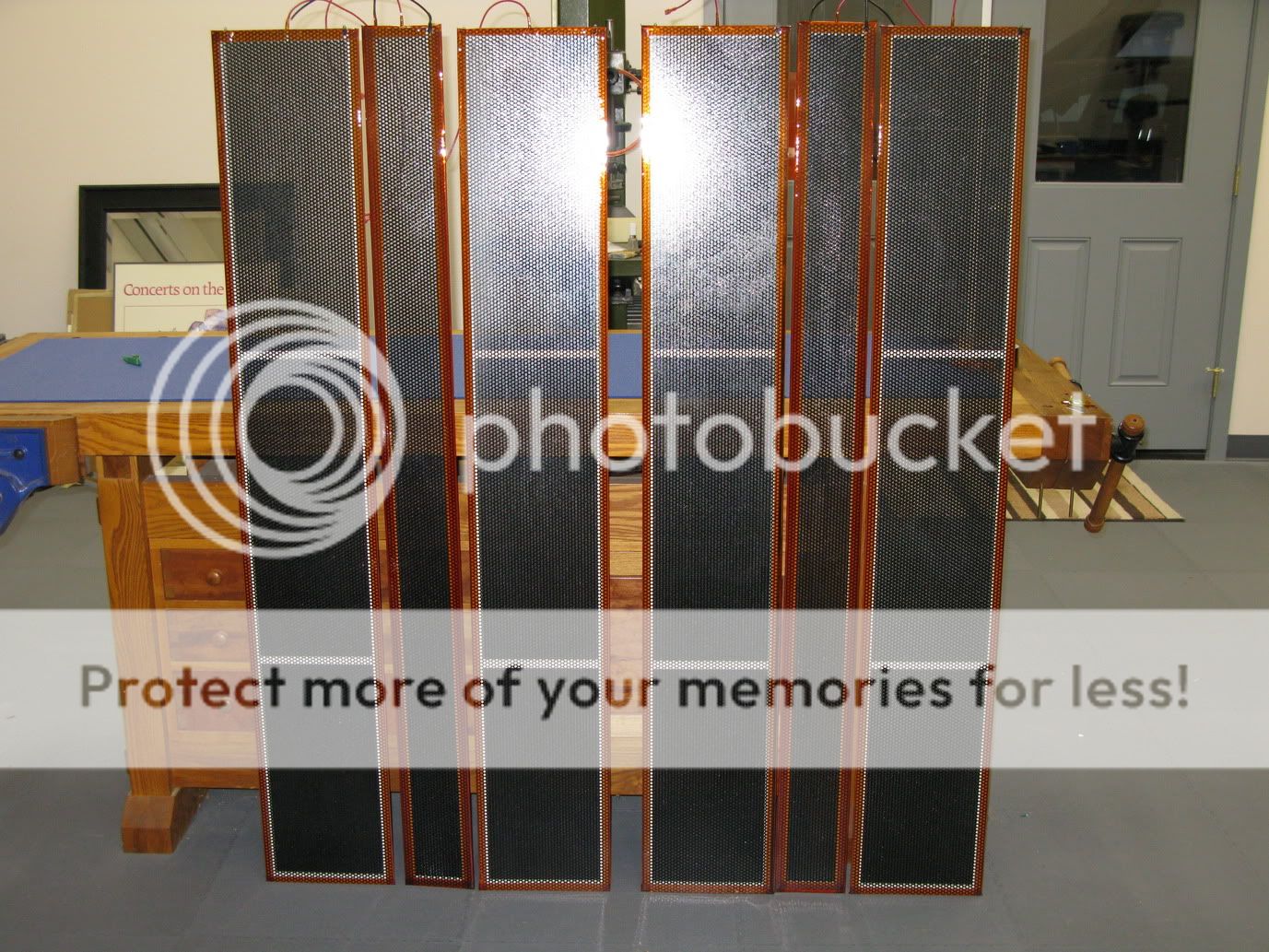
I finally finished all 6 panels. I'll test them today to make sure there is no arcing and put them away while I make the frames. I'll be using quarter sawn white oak and give them a Stickley (Mission) style.

Good job, nice looking panels!
What dimensions, tension, fim etc. did you use?
Roger
Thanks. I ended up using .25 mil mylar for all the panels as the .5 mil has never arrived after 3 weeks. The vendor is refunding my money. The large panels have .125" DS and have a radiating area of 8" X 59" (472 sq in).The small panels have a DS of .063" and a radiating area of 3.5" X 59" (206 sq in). I stretched the mylar slightly more than 1.5%. I don't know what tension that equated to, but I don't think it could be stretched more without breaking.
The overall size of the big panels is 60" X 9.5". The small ones are 5" X 60". The actual diaphram radiating area is posted above.
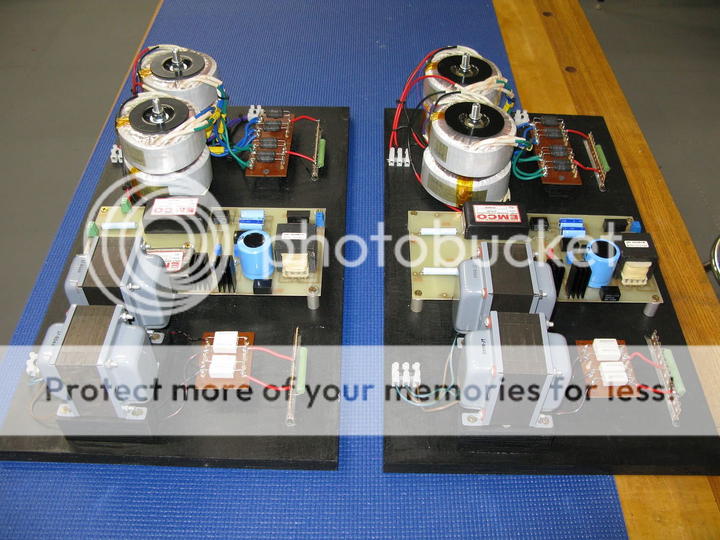
Well two steps forward and one step back. I finished both power suppliesfor my speakers. I designed them with two high voltage supplies per channel, one for the tweeter and one for the low/mid panel. The tweeter supply is adjustable from zero volts up to 5000 and the mid supply is adjustable from zero to 10,000 volts. Here are some pictures:
Also,I've decided to use a dynamic woofer for the low end up to about 300 hz. The whole system will be tri-amp'd.
As for the step backwards, both tweeter panels are arcing through the but joint of the foam spacer tape at high volume levels during testing. So I will be rebuilding those. I have some idead as to how to prevent that. Tomorrow is another day.🙂
A great way to insulate stators
OK, as stated earlier, my tweeter panels arced at high volume levels. The arcing occurred from stator to stator where the 3M foam tape butted together at the 90* corners. These have 2 coats of powder coat on them. I also added some coats of shellac, but the shellac didn't bond well with the powder coat so I had to remove it. After some brainstorming, I think I've come up with an excellent and easy method for putting a good insulating coating on the stators. Use 3M polyester resin (epoxy) and foam rollers. The resin is thick enough that it stays on the metal in and doesn't run off through the holes. With two coats and a little sanding between you can build up quite a thickness. and it comes out quite smooth. Here are some pictures:
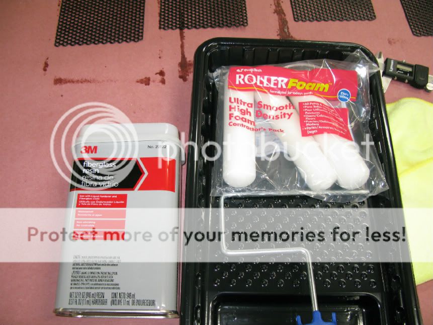
There is nothing wrong with spray painting, but that takes much more time and material. This is a quick and easy method. Of course you would have to spray your color coat first as the resin is pretty transparent. My startors are 20 gauge and the average measured thickness with the resin coating is .074 inches.
OK, as stated earlier, my tweeter panels arced at high volume levels. The arcing occurred from stator to stator where the 3M foam tape butted together at the 90* corners. These have 2 coats of powder coat on them. I also added some coats of shellac, but the shellac didn't bond well with the powder coat so I had to remove it. After some brainstorming, I think I've come up with an excellent and easy method for putting a good insulating coating on the stators. Use 3M polyester resin (epoxy) and foam rollers. The resin is thick enough that it stays on the metal in and doesn't run off through the holes. With two coats and a little sanding between you can build up quite a thickness. and it comes out quite smooth. Here are some pictures:
There is nothing wrong with spray painting, but that takes much more time and material. This is a quick and easy method. Of course you would have to spray your color coat first as the resin is pretty transparent. My startors are 20 gauge and the average measured thickness with the resin coating is .074 inches.
Last edited:
Very Cool !!
I have been eyeing that type of material, But I am using wire mesh,I was wondering if for sure it could possibly be sprayed on.
I have been working on my little panels and I have almost got them to withstand all of the voltage of my power supply at 13.8Kv.
But 10kv is my safety goal as right now I have finally got to 7kv and is probably enough.
Every time I think I have done it, a hole finally burst and I have to start over and add some more coats of clear or nail polish for certain small spots.
Silicone is used at times as well and seems to be one of the best but it is a little difficult to work with at times.
It has been a pain staking process.
Because once there is a failure it does not go away or cure itself and renders the panel useless.
But I am getting there the worse part is having to wait for the coatings to cure and I believe that as they cure a while they get thinner and this reduces their insulating factor,or at least this seems to be the case.
I once Had these panels to with hold at 7.5kv before.
Right now I have only one of the panels giving me a hard time and this time it was a super small chip off of the second layer (top, black) as the first layer was white and I can see it,with a micro whole in the middle of it.
Getting to 7kv is a real challange and working two twice that is quite a feat!!!
The sharp edges have been the very worst to deal and are were most of the failures occur.
I have had to strip down some of the spots and start over, as once a path for the arc occurs sometimes it is impossible to seal it because there is now a little channel of carbon molecules from the burnt material for the High voltage to flow through.
This is some thing you cannot see.
Keep on DIYing !!!
jer 🙂
If all this sounds as good as it look.....man i like to hear thes tranfourmer on my Acoustats....Why Acoustats.. just because that what my ear Knows the most..today anyway....................Thanks for all your time an the pic...keep it coming
Well, I finished rebuilding the upper mid/tweeter panels and they came out real nice. I increases the stretch of the film to1.8% and have the bias set to 4000kv. I can go higher, but they play so loud now that there is no reason to increase the bias. This time I built them with 1" wide foam tape and extended the tape 1/8" past the stator edges. So now the active film width is 3". The new resin coating method has worked so well that I'm going to redo the woofer panels with it. I'll keep trucking and posting.🙂
Very Cool !
I was wondering if you have a sound level meter can you post some figures?
I just finally got my little panels to withstand a bias voltage of up to 10kv without arcing today.
They should go higher but one stops at about 10kv and must be leaking at this point. That is about the safe limit of my supply anyhow even though it will produce 13.8kv.
Sadly I didn't have an spl meter to reference to the last time I ran them, But what a world of difference it was going from 2.8kv to 5.5kv and higher when the conditions were right.
It is going to interesting finally getting to a true 7kv to 10 kv bias.
This is alot of tension to be holding back.
Your panels are about the same width as mine but with 50 extra inches in length this about 7 times the surface area of my little panel this should be close to 9db more efficiency.
I will now Finally get to test them tomorrow for sure.
Keep up the Great Work!!!

jer 🙂
I was wondering if you have a sound level meter can you post some figures?
I just finally got my little panels to withstand a bias voltage of up to 10kv without arcing today.
They should go higher but one stops at about 10kv and must be leaking at this point. That is about the safe limit of my supply anyhow even though it will produce 13.8kv.
Sadly I didn't have an spl meter to reference to the last time I ran them, But what a world of difference it was going from 2.8kv to 5.5kv and higher when the conditions were right.
It is going to interesting finally getting to a true 7kv to 10 kv bias.
This is alot of tension to be holding back.
Your panels are about the same width as mine but with 50 extra inches in length this about 7 times the surface area of my little panel this should be close to 9db more efficiency.
I will now Finally get to test them tomorrow for sure.
Keep up the Great Work!!!
jer 🙂
- Status
- Not open for further replies.
- Home
- Loudspeakers
- Planars & Exotics
- Some More Questions On ELS Design