Hi All,
The built of my SSE has started.
So far so good. The soldering of the PCB has been very easy following the instructions. The high voltage and my lack of experience have given me enough 'respect' to not to try anything before being absolutely sure.
Now I am getting to the point of wiring all the parts and am not sure on some things so hopefully some of you can help me now and with the future questions that will come.
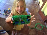
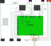
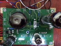
The PCB board is ready.
Now on the connection of the Edcor power connector I have a question what to do with the white and gold wire which is the CT for the brown wire?
Another question is about the supplemental capacitor. The diagram shows a + and - wire but the capacitor doesn't seem, to have a + or - connection. Can I connect it either way then?
Thank you and best regards,
Jock
The built of my SSE has started.
So far so good. The soldering of the PCB has been very easy following the instructions. The high voltage and my lack of experience have given me enough 'respect' to not to try anything before being absolutely sure.
Now I am getting to the point of wiring all the parts and am not sure on some things so hopefully some of you can help me now and with the future questions that will come.
The PCB board is ready.
Now on the connection of the Edcor power connector I have a question what to do with the white and gold wire which is the CT for the brown wire?
Another question is about the supplemental capacitor. The diagram shows a + and - wire but the capacitor doesn't seem, to have a + or - connection. Can I connect it either way then?
Thank you and best regards,
Jock
Attachments
Last edited:
I did this diagram for another poster awhile ago... maybe it'll help in this case too.
An externally hosted image should be here but it was not working when we last tested it.
The blue wire (Plate) goes to the center connection (O2) of the OPT primary connectors as well as to one side of the Triode/UL switch. The UL stripe wire goes to the other side of the switch. In the posted diagram, O1 is connected to the common of the Triode/UL switch
Ooopss

That could have gone pretty wrong. Good thing the kids keep me from moving too fast forward.
But now I am a bit confused.
Form the tubelab schedule I see only two wires coming form O1?
Jock
Attachments
Last edited:
Ok, let's see if this makes more sense... the schematic (I posted) and block diagram (you posted) don't match, so I did some closer looking and your diagram is right. I put the connector numbers on the schematic...the Triode/UL switch common goes to the middle, 02, and blue to 01. I hope this clears up any confusion.
An externally hosted image should be here but it was not working when we last tested it.
Adding a rectifier switch gave me a short burst of sound followed by a very loud building 'muehhhhhh' like when you disconnect or short the source.
With the rectifier of there nothing except a very silent hum in the speakers.
So the amp is working in a way.
Any suggestions on what to look for?
With the rectifier of there nothing except a very silent hum in the speakers.
So the amp is working in a way.
Any suggestions on what to look for?
Binbin, congrats on your working amp!
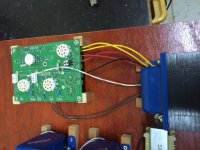
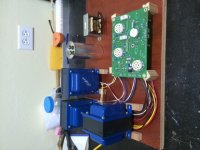
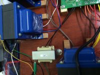
Denny here are some pictures.
Yesterday I had some success and got one channel to work. Amazing how much you don't know that you don't know LOL. I had the signal and ground mixed up on the RCA female plugs. I was looking on the internet and I guess the example I found was wrong...
So now I have the left channel working but only with the rectifier switch 'on'. The volume pot works also.
All the tubes are glowing.
The left channel does not work. I hear a very slight hum in the loudspeaker that, if I recall correctly, does not change in volume once I turn the volume up
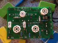
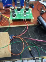
The pic's right after soldering and how it's all hooked up now.
Best regards,
Jock
Denny here are some pictures.
Yesterday I had some success and got one channel to work. Amazing how much you don't know that you don't know LOL. I had the signal and ground mixed up on the RCA female plugs. I was looking on the internet and I guess the example I found was wrong...
So now I have the left channel working but only with the rectifier switch 'on'. The volume pot works also.
All the tubes are glowing.
The left channel does not work. I hear a very slight hum in the loudspeaker that, if I recall correctly, does not change in volume once I turn the volume up
The pic's right after soldering and how it's all hooked up now.
Best regards,
Jock
Attachments
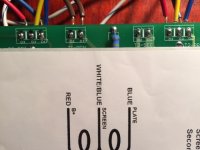
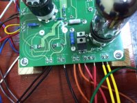
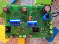
Jockaruba, look at your board near your rectifier tube socket you will see three pairs of holes
marked D3, TR1, and D4. It appears that you did not install these three components,
if not then you should place jumpers in these holes.
For a more detailed explanation read this entire thread......
http://www.diyaudio.com/forums/tubelab/266162-simple-se-signal-lost-driver-tube.html
marked D3, TR1, and D4. It appears that you did not install these three components,
if not then you should place jumpers in these holes.
For a more detailed explanation read this entire thread......
http://www.diyaudio.com/forums/tubelab/266162-simple-se-signal-lost-driver-tube.html
Thanks Jock.
It appears from the image that you have not used D3, D4 and TR1. It is good to have these components for better life of the rectifier tube.
Also check input connection to the PC board. I think you need to interchange the orange and black wires.
D3, D4 = 1N4007
TR1 = CL140
Thanks,
Bibin
It appears from the image that you have not used D3, D4 and TR1. It is good to have these components for better life of the rectifier tube.
Also check input connection to the PC board. I think you need to interchange the orange and black wires.
D3, D4 = 1N4007
TR1 = CL140
Thanks,
Bibin
Last edited:
Try swapping the inputs from your volume control around at the board connectors... red to orange; orange to red.... this is to see if the problem is at the board or before the board. As far as the missing diodes (D3; D4) and ICL (TR1), this will cause no output from your rect. tube, but won't affect the output from the hexfreds... I would recommend getting these parts (or the jumpers in their place for now) installed asap as it will allow you to use the rectifier tube circuit to troubleshoot the one working channel problem... in case you have a bad hexfred diode.
Thanks so far!
I'll be out trying to find the 1N4007 and CL140 (I hope I can find the last one here?)
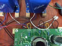
Some clarification on the last picture. The brown and black wire are soldered together where the black goes into the board and the brown to the rca.
After work I'll switch right and left around.
Best regards,
Jock
I'll be out trying to find the 1N4007 and CL140 (I hope I can find the last one here?)
Some clarification on the last picture. The brown and black wire are soldered together where the black goes into the board and the brown to the rca.
After work I'll switch right and left around.
Best regards,
Jock
- Status
- This old topic is closed. If you want to reopen this topic, contact a moderator using the "Report Post" button.
- Home
- More Vendors...
- Tubelab
- Some advise please during the built of my SSE