Bonsai said:My post #54 was done 'tongue-in-cheek'

Also, the new Natsemi LME49713 looks like it might do a better job here than the existing op-amp. I need to look into it a bit more and do some sims.
I've been playing with these opamps and they sound REAL good! Low noise and lots of output current-to drive a nice low Z passive circuit for the high end roll off...Then a second stage for an active boost below 1 kHz....and a third stage for the output buffer.
This would sound absolutely fabulous!
Bonsai said:I pulled the data sheet - they are CFA. 100Ohm drive capability. Fantastic stuff.
I thought so myself -- but then I saw the THD vs. output voltage plot, where for small voltages the thd rises enormously -- a sign of class-B output stage distortion?
Rüdiger
Onvinyl said:
I thought so myself -- but then I saw the THD vs. output voltage plot, where for small voltages the thd rises enormously -- a sign of class-B output stage distortion?
Rüdiger
Probably, but you have to expect that. High power consumption IC's have a rapidly shrinking market. Maybe THAT could make one, they certainly have access to a complimentary process.
BTW today is Moog's birthday and they just played about 1/2 an hour of Wendy/Walter Carlos. The Clockwork Orange piece still gives me the creeps.
maney said:
Well, let's start with the various forms of differential amps described in the early pages of Evolution from Operational Amplifier to Data Amplifier , a late-sixties paper from Analog Devices.
Thank's for finding that
A lot of people attribute the input stage on that last circuit to an 80's AES paper. I had been searching through our Analog Dialog archives and missed it.Re: Phoenix Systems P-100 phono preamp
Hi Dpuopolo.
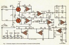
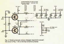
Here's the schematics of the Roberts MM preamp, I think.
The nice feature is the balanced input.
A long time ago, I do not remember where and when exactly, I saw about exactly the same comment as yours about this preamp.
To anybody, email me for full article.
dpuopolo said:This preamp built in the late 1980s (one of the absolute best I have ever heard) used a combination of passive and active EQ. The cartridge was buffered by a JFET, which had a capacitor across its source and drain to provide the (passive) RIAA roll off above 1 kHz. Then he used a second opamp stage with active eq for the boost that happens below 1 kHz. Finally, he rolled off things below 20 Hz for infrasonic protection.
This combination sounded better then ANY other I have heard, including any purely active or purely passive EQ circuit. Low Noise, dead accurate RIAA eq. and a sound that blew any CD player away.
I wish I still had one (Though I found one for sale online for 100 dollars).
http://cgi.audiogon.com/cgi-bin/cl.pl?preaphon&1215724261
This was the last product that John Roberts designed and marketed before he went to work for Peavey as their chief design engineer.
Phoenix Systems used to market audio kits in Popular Electronics in the '70s and '80s.
Hi Dpuopolo.
Here's the schematics of the Roberts MM preamp, I think.
The nice feature is the balanced input.
A long time ago, I do not remember where and when exactly, I saw about exactly the same comment as yours about this preamp.
To anybody, email me for full article.
Attachments
Nope
Those are the schematics for his P-10 preamp. The P-100 is a completely different design, and several years newer.
This design is 100% active EQ. The EQ network is in the feedback loop of IC-1D.
Don't get me wrong...the P-10 is still an EXCELLENT preamp!
The P-100 blows it away though!
We used to use the P-10 in broadcast. Note that the polarity switch actually switches between two sides of a differential output. We used to use this as a balanced output which allowed us to run the preamp output through patch bays, etc.
We'd simply put a TRS phone jack in place of the RCA output jacks and connect it to 1 and 2 on the switch.
Later, we used these preamps as 'balancers' for consumer CD players by using the aux inputs on the unit.
John actually began offering this as a no cost option on the preamp.
Some words from John Roberts himself
http://www.gearslutz.com/board/2043859-post38.html
http://www.gearslutz.com/board/2043859-post38.html
It depends...
The FETs that John used were quite quiet...and the Bipolars he used for the MC preamp even more so. Generally, I find that while balanced inputs might have a bit more hiss, they also have quite a bit less hum then single ended designs. To my ears at least, hum sticks out more then broadband noise does, simply because there's one frequency to 'hone in' on.
IIRC (and it's been 15 years) the P-10 was really quiet...actually a bit quieter then the P-100 (because the FET in the P-100 was running class A without feedback). The 75 us pole (high end roll off) was a selected cap just after this FET-which reduced some of its hiss by literally rolling it off. Then there was an active EQ stage that applied the necessary bass boost below 1 kHz.
The P-100 also did have a DC servo and line driver output. IIRC, John used a 5532 for the EQ and output stage. I used to replace the 5532 with an AD-712 because I thought it sounded a bit better. I'd LOVE to hear the P-100 with one of the new National duals in place of the 5532.
Sorry for the rambling post, but I'm typing what I remember as I clear the cobwebs in my mind...
Bonsai said:I would assume that a balanced input would be more noisey than a single ended input for phono amplification.
The FETs that John used were quite quiet...and the Bipolars he used for the MC preamp even more so. Generally, I find that while balanced inputs might have a bit more hiss, they also have quite a bit less hum then single ended designs. To my ears at least, hum sticks out more then broadband noise does, simply because there's one frequency to 'hone in' on.
IIRC (and it's been 15 years) the P-10 was really quiet...actually a bit quieter then the P-100 (because the FET in the P-100 was running class A without feedback). The 75 us pole (high end roll off) was a selected cap just after this FET-which reduced some of its hiss by literally rolling it off. Then there was an active EQ stage that applied the necessary bass boost below 1 kHz.
The P-100 also did have a DC servo and line driver output. IIRC, John used a 5532 for the EQ and output stage. I used to replace the 5532 with an AD-712 because I thought it sounded a bit better. I'd LOVE to hear the P-100 with one of the new National duals in place of the 5532.
Sorry for the rambling post, but I'm typing what I remember as I clear the cobwebs in my mind...
Bonsai said:From GRollins
' . . . the choice of active EQ invokes the same gain loss as passive EQ--roughly 20dB at 1kHz. That's inherent in the RIAA curve. Headroom problems are a function of circuit design and are easily avoided.'
Please explain quantitively - I don't understand th e gain loss at 1KHz of 20dB.
It's all a matter of perspective. Twenty Hertz is roughly 20dB above 1kHz; 20kHz roughly 20dB below. Only...1kHz isn't at the same level it was as it came from the cartridge since it's been amplified--40dB traditionally, more for moving coils.
The only realistic way to speak generically about an RIAA filter from my point of view is in terms of "gain unrealized." That pretty much levels the playing field when talking about active EQ, which cancels gain via feedback, and passive EQ, which uses a lossy passive filter to toss gain out the window between two stages. In either case, a 20Hz signal gets the maximum "realized" gain for the circuit. As such, the gain at 1kHz suffers a 20dB loss by comparison.
Most specs for phono stages quote the gain at 1kHz. There's nothing special about that frequency and nothing to recommend it except that it gives an apples to apples basis for gain comparison. People could just as easily quote the gain at 20Hz and, honestly, I think that would be more descriptive in some ways, since it's somewhat more indicative of what's being asked of the circuit in terms of overall gain. If you view it from that perspective, a "40dB" phono stage is actually 60dB at 20Hz. That way, at least through the eyes of the person building the circuit, you're reminded that you need to provide at least that much gain for things to work out. If you were, for instance, to use a passive RIAA filter with a 40dB gain cell, you wouldn't have a 40dB phono stage (in the 1kHz sense) by the time you were done, you'd have a 20dB phono stage due to losses in the EQ. But if you set out to design a 60dB gain stage, you'd have your 20Hz at +60dB, your 1kHz at +40dB, and your 20kHz at -40dB.
No, I'm not out to try to convince the world to change the way they specify gain for a phono stage--I'd have more luck tilting at windmills. It's just my way of reminding myself that I need more gain than what shows up in the 1kHz spec.
Or you could simply say that there's a 20dB insertion loss into the RIAA filter, which is the way many choose to look at it. Same difference.
Grey
Onvinyl said:
I thought so myself -- but then I saw the THD vs. output voltage plot, where for small voltages the thd rises enormously -- a sign of class-B output stage distortion?
Rüdiger
0.00008 % THD is too high for you? That's the 1 kHz THD at 1.4 volts RMS output.
What many here don't understand is that at low signal levels, NOISE is likely to make up most of the 'distortion' component.
Bssides, every distortion spec they publish shows the distortion components down better then 100 db. What's wrong with THAT?
0.00008 % THD ...
more perfect than reality, probably lower than acoustic instruments naturally produce and the air will create at usual listening distance. Some people should seriously consider to stop messing around and fooling themselfs and other believers with those completely unreliable and worthless simulation figures.
more perfect than reality, probably lower than acoustic instruments naturally produce and the air will create at usual listening distance. Some people should seriously consider to stop messing around and fooling themselfs and other believers with those completely unreliable and worthless simulation figures.
Hugh,
would you first kindly read this intimating my basic view.
http://www.diyaudio.com/forums/showthread.php?s=&threadid=118826&perpage=25&pagenumber=1
would you first kindly read this intimating my basic view.
http://www.diyaudio.com/forums/showthread.php?s=&threadid=118826&perpage=25&pagenumber=1
AKSA said:Gee Ogir,
Is that really the truth? You place little importance on these figures?
Are there any examples of amps with 0.0008% distortion which actually sound BAD??
Cordell's 20 year old error correction amplifier has 0.0007%, the ExtremA has 0.0005%, the PGP power amp has 0.0001%, and Halcro has <0.0001%. Perhaps someone can comment on the sound of these.
AKSA said:Are we measuring the wrong thing?
Put simply, yes.
- Status
- This old topic is closed. If you want to reopen this topic, contact a moderator using the "Report Post" button.
- Home
- Source & Line
- Analogue Source
- Solid state phono preamp design philosophy