Is headroom really an important issue if the supply voltage is at least +-15 volts and if a totally passive correction is chosen. I have never measured how much a click in the LP will generate. All my RIAA amps so far have been the active variant.Bonsai said:Talking about the topology, I do have a predilection for the active a approach due to headroom requirements on the passive approach and possibly higher overall noise.
On a MM I guess 3mV output at 1Khz. Assume at 20Khz 20dB above this (yes, I agree there is not much musical energy at 20Khz but as you point out there's clicks and pops which probably do have quite a bit of high audio frequency content). That takes us to c. 300mV. Then add some overload margin - take your pick here - at 1Khz a lot of people look for around 26dB - lets call it 6dB at 20kHz - now we are at 600mV. If you need an out put of 300mV midband, that means a typical gain of 100 . . . . so now we are at 30V output at 20Khz
Of course I've over simplified a bit to illustrate the point. If you use a passive approach, the first stage gain will have to be limited to overcome this problem, and you will generally need a second stage of gain. However, this will mean you have to accept more noise, since ideally you want to put as much gain up front for lowest noise.
So, maybe this is why passive topology is a better fit for tubes where you can get the headroom.
BTW, John Atkinson did a review of a phono stage about a year back that used the passive approach (solid state I have to say) and remarked that it had a great sound, but overload capability was only 6dB.
my suggestion is to use a cfa op amp as the output buffer/additional loop gain stage in a composite op amp with the active riaa feedback enclosing both op amps
for mc the input op amp could be one of the "short list" AD797, LT1028/1115, LME49710, AD743/5 of suitably low noise (at low frequency - many fast opamps have 1KHz+ 1/f corner frequency) op amps
these op amps all have low open loop gain corner frequencies so implementing at least one riaa roll-off time constant as active feedback is ideal even by "feedback critic" Otala's criteria - the feedback factor remains nearly constant over the entire audio frequency range with active riaa and high gain/low corner frequency dominant pole compensated op amps
Onvinyl said:Is there any alternative to a diff-amp when making a balanced input stage in this world (that has reasonable cmrr)?
Rüdiger
Sure. You can take a pair of CF opamps (AD844, say, since you don't want any long-tailed inputs). Apply balanced signals to the + inputs, tie the - inputs through a resistor to define the gm, add gain-setting resistors... oh, you wanted feedback? You can work it that way, too.
Or if you want the circuit unbalanced past the input, there's the classic use of a unity gain inverter, seen more often going the other way in eg. older Audio Research power amps, to drive the balanced gain stages from the SE input. SImple case, take two gain -1 amps, one of which has to have a summing node. One input goes through the other inverter then sums into the second along with the second input. Play with the gain structure to suit your needs. Implement the inverters with opamps (long tailed or not), SE transistor stages, tubes even.
Or, of course, you could use a transformer.
-- Martin "fifty ways to love your lever" Maney
Bonsai said:lets see some circuits maney.
And leave your lever out of it.
Well, let's start with the various forms of differential amps described in the early pages of Evolution from Operational Amplifier to Data Amplifier , a late-sixties paper from Analog Devices. Although some of the circuits presented assume amps that almost have to have long-tailed input stages, a number of them would be amenable to other implementations. The righthand circuit in Fig 8 was what I was trying to handwave talking about inverters, but the other version could probably be built from single ended gain stages without much more effort. The pair of 844s would look very much like the circuit of Fig 9 (for the closed-loop version), with only some additional consideration of the effect of the feedback resistor's magnitude on the OL gains needed.
OTOH, there's room for disagreement that the cross-coupled complementary input stages of a pair of 844s isn't an odd variant of the normally long-tailed differential pair. If that doesn't immediately make sense, look for Grey's recent treatise on how the FET version of that sort of thing works in his GR-25 amplifier, which is what got me started thinking about it that way.
I don't need to draw a picture of using a transformer for this, right?
-- Martin "haven't got an easy way to send you graphics right now anyway"
From GRollins
' . . . the choice of active EQ invokes the same gain loss as passive EQ--roughly 20dB at 1kHz. That's inherent in the RIAA curve. Headroom problems are a function of circuit design and are easily avoided.'
Please explain quantitively - I don't understand th e gain loss at 1KHz of 20dB.
' . . . the choice of active EQ invokes the same gain loss as passive EQ--roughly 20dB at 1kHz. That's inherent in the RIAA curve. Headroom problems are a function of circuit design and are easily avoided.'
Please explain quantitively - I don't understand th e gain loss at 1KHz of 20dB.
Phoenix Systems P-100 phono preamp
This preamp built in the late 1980s (one of the absolute best I have ever heard) used a combination of passive and active EQ. The cartridge was buffered by a JFET, which had a capacitor across its source and drain to provide the (passive) RIAA roll off above 1 kHz. Then he used a second opamp stage with active eq for the boost that happens below 1 kHz. Finally, he rolled off things below 20 Hz for infrasonic protection.
This combination sounded better then ANY other I have heard, including any purely active or purely passive EQ circuit. Low Noise, dead accurate RIAA eq. and a sound that blew any CD player away.
I wish I still had one (Though I found one for sale online for 100 dollars).
http://cgi.audiogon.com/cgi-bin/cl.pl?preaphon&1215724261
This was the last product that John Roberts designed and marketed before he went to work for Peavey as their chief design engineer.
Phoenix Systems used to market audio kits in Popular Electronics in the '70s and '80s.
My post #54 was done 'tongue-in-cheek'

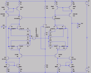
Rudiger, nice design - .001 simmed distortion. Put a bit of GNF around that thing and you'd easily get to 100ppb!
I see a lot of designs with JFET's but my concern is over matching and availability (P-chan seems to be the main issue).
I have been looking at Dennis Collins cct again and really like the tradeoffs he has made wrt to overload and noise. I'm wondering however if one of the stages could be eliminated (3rd one) for the same/similar performance. Also, the new Natsemi LME49713 looks like it might do a better job here than the existing op-amp. I need to look into it a bit more and do some sims.
- Status
- This old topic is closed. If you want to reopen this topic, contact a moderator using the "Report Post" button.
- Home
- Source & Line
- Analogue Source
- Solid state phono preamp design philosophy


