Re: Just an open source experiment
Amazing what you guys in India manage to create!
But seriously get rid of those ZC opto device, and that 200 Hz osc. which obviously is not synchronized to the mains frequency (I don't think you run fancy PLL here, do you? ), you will probably encounter random performance.
Cheers Michael
Workhorse said:
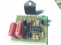
Yes, its true that this is a Zero-crossing opto-coupler....but i have found through experimenting that this Stuff really WORKS....Strange....
Amazing what you guys in India manage to create!
But seriously get rid of those ZC opto device, and that 200 Hz osc. which obviously is not synchronized to the mains frequency (I don't think you run fancy PLL here, do you?
), you will probably encounter random performance.Cheers Michael
Hi Eva,
this went to sleep for a while.
Thanks for waking it up and posting the updates.
That 5kVA makes my 750VA look puny!
My browser can't find http://eva.eslamejor.com/softst0.gif
But you can see the schematic here:-http://www.diyaudio.com/forums/attachment.php?s=&postid=1150054&stamp=1173080632
this went to sleep for a while.
Thanks for waking it up and posting the updates.
That 5kVA makes my 750VA look puny!
My browser can't find http://eva.eslamejor.com/softst0.gif
But you can see the schematic here:-http://www.diyaudio.com/forums/attachment.php?s=&postid=1150054&stamp=1173080632
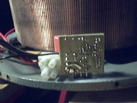
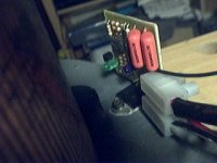
This little toy is assembled again and ready for use (note how tiny a standard CD looks in comparison). The circuit breaker tripping problem is completely solved because the soft start circuit is wired after the own circuit breaker of the variac, so it's also covering the four 1KVA toroid isolation transformers that follow the variac and the own inrush current of my prototypes. That built-in circuit breaker has proven to be a quick and comfortable way to apply and remove power to the circuits under testing.
Attachments
Re: Hi!
Actually I did it in a hurry some time ago, but I forgot to publish the pictures.
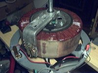
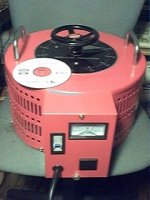
The same as at high voltages. The manufacturer claims that it can handle 20Arms, but I doubt... Also, one of the main drawbacks of variacs at low voltages is very high leakage inductance due to a lack of auto-transformer coupling.
The main drawback of that circuit is the very low drive current available for the optocoupler. The datasheet states 30mA for worst case, but less than 6mA are provided with 230V mains. Also, the 15K value for the ballast resistor is far from optimum, being something like 3.3K more suitable, but a ballast capacitor would be a far better alternative as it does not produce heat and does not draw DC.
The 18V zener dains the excess current provided by the ballast capacitors thus limiting the supply voltage.
AndrewT said:Hi Eva,
this went to sleep for a while.
Thanks for waking it up and posting the updates.
That 5kVA makes my 750VA look puny!
My browser can't find http://eva.eslamejor.com/softst0.gif
But you can see the schematic here:-http://www.diyaudio.com/forums/attachment.php?s=&postid=1150054&stamp=1173080632
Actually I did it in a hurry some time ago, but I forgot to publish the pictures.
luka said:Hi
How many amps can this variac put out at low votages, limited by wire size?
The same as at high voltages. The manufacturer claims that it can handle 20Arms, but I doubt... Also, one of the main drawbacks of variacs at low voltages is very high leakage inductance due to a lack of auto-transformer coupling.
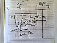
zeonrider said:This schematic works perfectly with any inductive loads.
Sharp eye can see MOC3040 zerocrossing detector, with opto-triac.
Regards zeoN_Rider
The main drawback of that circuit is the very low drive current available for the optocoupler. The datasheet states 30mA for worst case, but less than 6mA are provided with 230V mains. Also, the 15K value for the ballast resistor is far from optimum, being something like 3.3K more suitable, but a ballast capacitor would be a far better alternative as it does not produce heat and does not draw DC.
sam9 said:Eva,
I assume the 18V zener provides the power for the comparators?
The 18V zener dains the excess current provided by the ballast capacitors thus limiting the supply voltage.
Hey Eva,
For some reason the original gif at the beginning of the tread is no longer accessible. Could you point me to the latest rev of the soft-start circuit.
BTW: I noticed another user on these boards said that you had a corrected version of the PA150 PCB design.
Any chance I could get a copy?
Thanks,
eris
housing said:Hello Eva,
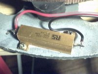
I have some 50 ohm 50 Watt resistor sitting on the shelf. Can I use one of them in place of the 10 ohm resistor?
It's too high a value, consider two in parallel.
eris said:Hey Eva,
BTW: I noticed another user on these boards said that you had a corrected version of the PA150 PCB design.
Any chance I could get a copy?
Thanks,
eris
I can't remember anything called PA150. Could you provide a link to some related post or thread?
- Status
- This old topic is closed. If you want to reopen this topic, contact a moderator using the "Report Post" button.
- Home
- Amplifiers
- Power Supplies
- Soft-start circuit with no relays and no aux. transformers