There is no added noise at all (electrical or acoustic) because the 10Khz oscillator guarantees that the triac is kept continuously triggered (I have just checked with oscilloscope), remember that triacs are very slow devices that take a lot of time to unlatch and turn off.
That satisfies my greatest concern.
Apart from changing the balast cap, are there any other considerations for use with 120v mains?
Eva said:
Then you end up with 2V @20A drop from the diode bridge plus another 1.5V @20A from the IGBT (assuming a standard speed one is chosen). Compare that to the 1.5V @20A from the triac, which has no rival when it comes to solid state switching of AC mains. If you want optocoupler triggering, consider a MOC3020 optotriac, and note that it does not require an additional power supply.
Great but it seems expensive and very hard to get. Compare it to the standard parts employed in my circuit or to those 8-pin low-cost PICs available in every store (with dozens of webs showing free programmer plans and code).
Yeah the voltage Drop would be Great in comparision with Triacs...I think that the optocoupler Triggering based softstart would be much much easier.....
The Atmel IC is expensive but it Features a ONE CHIP SOLUTION also on other hand...
BTW: your circuit is also great as its easier to build from LOW COST parts and easier for everyone to develop it....
The 5KVA variac arrived yesterday (that's one more reason for a soft start). Actually, the transformer element is not as big as the massive case would suggest, and it's not as well built as I would like, but I got essentially what I paid for so I can't complain this time. I have put a conventional CD on it to make a better impression of the size...
An externally hosted image should be here but it was not working when we last tested it.
A NE555 will draw 10mA by itself thus requiring a much bigger ballast capacitor, while a LM339 draws 0.7mA (typ.) You may consider the CMOS version of the 555 (ICM7555, LMC555) but you would still need two timings, one for the oscillator and other for the soft-start itself, so a 556 would be required instead. In general I find LM393, LM339, LM358 and LM324 very versatile.
Must be the most complex soft-start what I have seenWorkhorse said:Hi Eva,
Here is my idea....simple version using IGBT as a switch and Driving it from PVI coupler, just an idea...only
for PVI have a look at this
http://www.irf.com/product-info/datasheets/data/pvin.pdf
The LED Trigger circuit could made easily with few passive components for working from mains directly
K a n w a r

I think I'll stick around with 24v relays powered by ballast cap, 0.22-0.33uF is around rigth value for typical 16A pcb relay. (please note that 230v ac-rated cap is needed)
Ballast cap, small bridge rectifier, 22u/35v cap, power resistor and relay is all you need, total component cost is maybe 3-4 euros.
Look up the Motorola TDA1185. Here's a link to the pdf. TDA1185
This chip is a phase angle controller that runs off the line without xfmrs etc. The app notes give excellent details for a softstart. I adapted it for an outdoor light that automatically comes on at dark and walks on slow when power is applied so the bulb never burns out . Note that the app notes shows electrolytic filter caps with the polarity reversed.
This chip is a phase angle controller that runs off the line without xfmrs etc. The app notes give excellent details for a softstart. I adapted it for an outdoor light that automatically comes on at dark and walks on slow when power is applied so the bulb never burns out . Note that the app notes shows electrolytic filter caps with the polarity reversed.
When I was trying to build a triac soft start, I would run across mention of how to chose a snubber for use with an inductive load. Phase angle controllers didn't eliminate this requirement as far as I could see. It sounds simple, just follow the formula for required snubber value -- until you measure the inductance of a power transformer primary the required value for the snubber cap it outside the range of common value.
I didn't keep notes so if anyone wants to check it out and post it here, please do.
As I read it EVA's circuit eliminates the requirement for a snubber.
I didn't keep notes so if anyone wants to check it out and post it here, please do.
As I read it EVA's circuit eliminates the requirement for a snubber.
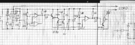
Hi everyone, this is mine attempt at this.
Input is a window comparator controlling a transistor which shorts the cap during zero crossing so we can have a nice inverse ramp, which is in turn is compared with slow ramp from another cap charging.
So far I need to verify triac triggering, power supply and possibly make an on/off toggle button from a last comparator of LM339.
The overall cost of the circuit is like ~2 euro if you have a normal local retailer.
Attachments
It's not relay a "soft - start" -- an active FET limiter which appears in Pressman's "Switching Power Supply Design and Optimization" -- detects the zero crossing and allows the current to ramp with the voltage.
I am tired of blowing diodes:
I am tired of blowing diodes:
An externally hosted image should be here but it was not working when we last tested it.
Hi,
I am going to experiment with Opto Traic Driver MOC3041 which has inbuilt Zero Crossing Detector, thus one could Trigger the LED with Proportional Drive using PWM to limit the inrush current.......through Traic...while still conducting in ZC region
regards,
K a n w a r
I am going to experiment with Opto Traic Driver MOC3041 which has inbuilt Zero Crossing Detector, thus one could Trigger the LED with Proportional Drive using PWM to limit the inrush current.......through Traic...while still conducting in ZC region
regards,
K a n w a r
VEC7OR said:Um what is this thing below exactly for ? What does it control ?
Sorry, forgot to connect the gate. The FET doesn't operate in the linear region, switches on at the zero crossing. See Pressman cited above.
Workhorse said:Hi,
I am going to experiment with Opto Traic Driver MOC3041 which has inbuilt Zero Crossing Detector, thus one could Trigger the LED with Proportional Drive using PWM to limit the inrush current.......through Traic...while still conducting in ZC region
regards,
K a n w a r
Hi Kanwar, do you feel followed by me?
Just FYI you can not PWM modulate with that optocoupler, because it triggers always at the beginning of every half cycle when the LED is on.
If you want to PWM you must find a triac optocoupler without that zero crossing stuff.
Cheers Michael
Just an open source experiment
Hi Michael,
I love Challenges and also the Challengers too....
I feel good if someone follows my path.....
Yes, its true that this is a Zero-crossing opto-coupler....but i have found through experimenting that this Stuff really WORKS....Strange....
The LED was Triggered from SG3524 wired as OR configuration...A slow ramp [simple RC to define a delay]was injected to its opamp and OSC set at 200Hz, the PWM was obtained with DTC rising from 10% to 100% and the inrush current from Traic was just 10 amperes as opposed to 90A...[without any limiting]....
I still donot get it why its so, because the opto is ZC type not a Random Trigger type....besides this a Random Triggering Opto circuit triggered from NE555 timer which inturn was triggered from another ZCD circuit was also just doing the same.....
Any drawbacks ....
Could someone explain is it right or wrong in practice...
regards,
K a n w a r
Ultima Thule said:
Hi Kanwar, do you feel followed by me?
Just FYI you can not PWM modulate with that optocoupler, because it triggers always at the beginning of every half cycle when the LED is on.
If you want to PWM you must find a triac optocoupler without that zero crossing stuff.
Cheers Michael
Hi Michael,
I love Challenges and also the Challengers too....
I feel good if someone follows my path.....
Yes, its true that this is a Zero-crossing opto-coupler....but i have found through experimenting that this Stuff really WORKS....Strange....
The LED was Triggered from SG3524 wired as OR configuration...A slow ramp [simple RC to define a delay]was injected to its opamp and OSC set at 200Hz, the PWM was obtained with DTC rising from 10% to 100% and the inrush current from Traic was just 10 amperes as opposed to 90A...[without any limiting]....
I still donot get it why its so, because the opto is ZC type not a Random Trigger type....besides this a Random Triggering Opto circuit triggered from NE555 timer which inturn was triggered from another ZCD circuit was also just doing the same.....
Any drawbacks ....
Could someone explain is it right or wrong in practice...
regards,
K a n w a r
Um stupid question about all of this stuff, as far as I gone modelling it, in case of SMPS with caps connected to a bridge, no matter how small the phase angle is there still is substancial current pulses, duration is short though, how bad it will be on a triac ? Its pretty clear whats on what in the case of ballast resistance, but in the case of triac chopping I cant decide what to use, and now I'm leaning toward classic relay-resistor stuff.
- Status
- This old topic is closed. If you want to reopen this topic, contact a moderator using the "Report Post" button.
- Home
- Amplifiers
- Power Supplies
- Soft-start circuit with no relays and no aux. transformers