stoolpigeon said:Mark, could you elaborate on the "properly designed" drive system.
Since this thread is all over the place I have some general belt drive questions for anyone:
1. merits of different belt profiles ie tape, thread, flat, round and square.
2. what profile drive pulley is best for using magnetic tape and if it is flat then how do you stop the tape wandering.
3. does the phasing capacitor for a synchronous motor change with supply voltage/frequency and how do you calculate it, eg my old Ariston uses 0.22uF as standard but should it be changed for 80 volt operation where motor vibration is lower.
Q 0. No, I regret saying anything, forget I spoke.
Q1. All have some merits and some disadvantages. Which is best depends on the application, most especially the motor in use. In general thin and wide is better than round or square. Another generalisation is that stiffer material (tape, thread) gives less creep but more slip and transmits more motor noise.
Q2. I believe a very slight crown is best but I have no experience.
Q3. The capacitance required depends on the drive frequency, the motor winding inductance and the phase shift required. Assuming you want 90 degrees the usual LC tank equation applies: 2piF = 1/SQRT (L.C)
Thanks Mark, just one more motor question.
Are you familiar with a Papst dc motor that has a flat square body with a circuit board jammed in the middle?
I bought it from Jaycar a while ago advertised as a turntable motor and when I took it to a local hifi shop they said it was from an Oracle player.
Anyway do you know what type of motor it is and if it is any good. I connected it to 24V and it seems to run quite slowly and smoothly.
stoolpigeon said:Are you familiar with a Papst dc motor that has a flat square body with a circuit board jammed in the middle?
Not familiar with that particular motor but I'll bet you it's what is known as a brushless DC or BLDC motor. These are basically 3 phase AC synchronous motors which incorporate switching circuitry so that they act like DC motors, making life much simpler when designing them into a servo loop. They generally have hall effect sensor outputs which put out a pulse train which can be used with a PLL to drive the loop.
They can be used in turntable drives. I personally don't like servo loop motor controls for turntables but there are many who do - virtually every Direct Drive turntable on earth uses them.
Hi,The error from the mains will swamp the pulley calculation error
based on the somewhat conflicting evidence I have seen, both in my recent trawl and from before, I still believe that mains frequency variations of +-1% or +-2% will swamp speed variations of a belt drive deck, which is easily capable of being made and measured to better than +-0.5% and with care approaching +-0.1%. That's a 1/10 of a turn error in three minutes.
Yes, I really do believe the belt drive system can be made to be ten or more times more accurate than the tolerance allowed in the mains frequency.
") /sreten.
/sreten.stoolpigeon said:How then can you set turntable speed if there is no readily available reference frequency?
With one of these and a strobe disc. Use the brightest red LED you can buy, I used a 13,500mcd LED.
Attachments
Few graphs to look at. You can decide how much frequency deviation will cause a problem with your turntable.
First is a weeklong graph: http://www.just4sheep.com/site/images/week.pdf
First page (red) is the weighted average over a period of 5 minutes. This would be long term deviations that significantly affect the speed of a motor. Minimum is 59.94 Hz, maximum 60.05 Hz. Accuracy of instrument is +/- 0.01 Hz.
Second page (light blue) is the same monitoring period and input signal, but no averaging. This is a cycle-by-cycle minimum/maximum plot. Obviously, range will be greater, from 59.93 Hz to 60.06 Hz. I was expecting a greater range when looking at cycle by cycle, but then again, we experienced no upstream faults during the week long monitoring period.
Both graphs are fairly well centered at 60.0 Hz, and are very slightly correlated with day/night patterns.
Next graph is one performed over the period of one hour at a different site, different time frame:
http://www.just4sheep.com/site/images/hour.pdf
This will amount to a 3 second weighted average, which I think is representative of what would produce a physical jitter while overcoming any inertia in the turntable (wild guess, here).
Deviations range from 59.93 Hz to 60.03 Hz, and are not centered around 60 Hz.
Don't know if this is of any value to anyone, other than for me to think that the frequency stability on a practical level is very good in America. Whether or not it audibly affects your music, I can't say. For design purposes, I would assume frequency stability is +/- 0.05 Hz. Faults, load dumps, etc are rare enough that I don't know I would be concerned about them.
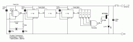
Thanks EC8010 but my feeble brain calculates your circuit ends up with 100Hz (50Hz crystal) so have I missed anything?
While I'm at it and sort of on topic I have decided to resurrect my Audio Amateur turntable supply designed by Gary Galo and using XR....... (sorry it's in the shed).
I built it and had a tech adjust the sine wave output but never connected it.
I need some advice on which amp and stepup transformer to use. Am I better to have a high power amp with a low stepup or a low power amp with a high stepup? Even then if I pick an amp what is the best operating point for it? Will a bigger VA transformer be better even though the motor only needs a few watts?
I even remember Pink Triangle saying they added some distortion to the sine wave in their power supply for the LP12 but maybe that was just advertising.
Sorry but I was and am still racked by indecision.
stoolpigeon said:Thanks EC8010 but my feeble brain calculates your circuit ends up with 100Hz (50Hz crystal) so have I missed anything?
That's right. A lightbulb or fluorescent doesn't know about polarity, only peaks, so it effectively rectifies mains and produces 100Hz pulses, hence strobe discs are actually calculated for 100Hz illumination.
stoolpigeon said:
I need some advice on which amp and stepup transformer to use. Am I better to have a high power amp with a low stepup or a low power amp with a high stepup? Even then if I pick an amp what is the best operating point for it? Will a bigger VA transformer be better even though the motor only needs a few watts?
I even remember Pink Triangle saying they added some distortion to the sine wave in their power supply for the LP12 but maybe that was just advertising.
The amp should be relatively robust. I've experimented with everything from Class D and Tripath chip amps, through LM1875s to small discrete Class A amps I designed and built myself - I even gave EL34s and KT88s a go.
The LM1875 is probably the easiest to get sorted.
The transfomer should be somewhat over-rated in VA terms and you must be careful about magnetisation current - if it's too high it will overload the amp. I find toroids rated at 150% of required power to work very well.
One thing to watch is that transformer voltage ratings always include a regulation allowance and if you reverse the trafo (as a step up) you also reverse this. A10% regulation measn you need a traf which has an apparent turns ratio about 20% higher than required.
As an example if you bought a 240 V to 24 V trafo you would expect it to have a turns ratio of 10 and thus if you fed the secondary 24 volts you'd get 24 out the primary.
But you won't.
The winder will have made the turns ratio somewhere about 9 and allowed for about 10% voltage drop on load to get the right voltage. If you feed the secondary with 24 volts you'd then get 216 volts unloaded and at full load the 10% sag would put you under 200 volts.
I used a back to front 240:12 Vac transformer connected to a little 50W into 8r0 amplifier to generate the 120Vac the motor required.stoolpigeon said:had a tech adjust the sine wave output but never connected it.
I need some advice on which amp and stepup transformer to use. Am I better to have a high power amp with a low stepup or a low power amp with a high stepup? Even then if I pick an amp what is the best operating point for it? Will a bigger VA transformer be better even though the motor only needs a few watts?
I attenuated the input signal to the amp and found that the motor needed 90Vac to start reliably but would run on just 75Vac. I suspect wow would be a real problem with excessively low voltage so I settled for running at 100Vac and it seemed to work quite well with a mains frequency input. I never finished the crystal referenced 50Hz/67.5Hz supply. Two standard TV crystals produce exactly these frequencies when divided down.
The next stage was to be using the other half of the stereo power amp and a second transformer to generate the 90degree phase angle for the synchronous motor.
I wonder if 350Vce transistors running on +-180Vdc rails could produce 110/120Vac reliably? no transformers. We only need 5 to 10W of output .
Just checked 1pair MJL4281/4302 on +-183Vdc, produces 20W into 730r no problem. Even 60degree phase angle keeps the load line just inside the 25degC SOAR. 20W into 730r is 120Vac. But the motor load is considerably less. I wonder what start-up currents are like? Oh, I used 1000uF 200Vdc caps as smoothing in the model.
Hi Andrew,
Why not a nice little VCA circuit in front of the 50Hz amp, configured so voltage would ramp nicely upon startup.
No problem with startup currents and the belt would also benefit from a smooth start.
Of course the amp should be designed strong enough to withstand full voltage into a stalled motor and/or have some form of current limiting.
Thoughts?
I have managed to get my Audio Amateur supply running through an old PA amp and a step up transformer and it works fine.
These synchronous motors vibrate an incredible amount when you just hold them in your hand! I thought there was something wrong with the PS but I connected the motor back to the original Ariston supply and also tried a Rega motor and the results were similar. No wonder people try dc motors!
I will experiment with different voltages and try to vary the phasing capacitor to see if I can reduce the motor vibration. I wanted to ask if there were any problems running the motor at a vastly different speed by varying the drive frequency. I'm thinking I could mount the motor offboard and drive the outside of the platter or use the Rega motor which has a smaller pulley than the Ariston. Assuming the motor can spin the platter steadily are we just interested in the lowest vibration?
- Status
- This old topic is closed. If you want to reopen this topic, contact a moderator using the "Report Post" button.
- Home
- Source & Line
- Analogue Source
- So How's it done?