That's what I was wondering, too. It seems to me that TASCAM was telling the truth, this really is not a problem. A tiny, tiny, tiny amount of noise, at frequencies far above what we humans can hear - it simply does not matter at all.... those combs are all ~100dB down and in the ultrasonic, why do you care about them?
Gino, I think you have a very nice piece of audio electronics there, just enjoy it! Not so long ago, noise performance this good would have only been possible for JPL/NASA!
-Gnobuddy
Hi ! those bumps will go away one day.
I will spend the rest of my life playing with interface for pc ... i am sure of this.
The pc has become my main and only source of entertainment.
Because it is hugely flexible.
But it is also a little nasty piece of electronics.
But first i need to understand how to get those graphs of noise ... i see mentioned ARTA software as a valid tool.
Thanks for all the very kind support.
Kind regards, gino
Hi ! welcome from the Lounge !
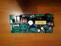
I am attaching a picture of the smps pulled out from the box.
I checked and there is one input for the 230V and just one output with 4 wires but they are connected together 2 by 2, and 2 are grounded.
So in the end it is a single output power supply !!! good !!!
The tricky part will be how to measure the Vout now.
However a possible way would be use a good quality smps for laptop (usually they are 19-20VDC) and put inside another regulations stage to step down the voltage to the one needed.
I would very much prefer to avoid a transformer inside the box.
Very much.
But now i have to measure the Vout ... damn ...
Thanks a lot again, gino
Attachments
Last edited:
That's what I was wondering, too. It seems to me that TASCAM was telling the truth, this really is not a problem.
A tiny, tiny, tiny amount of noise, at frequencies far above what we humans can hear - it simply does not matter at all.
Gino, I think you have a very nice piece of audio electronics there, just enjoy it! Not so long ago, noise performance this good would have only been possible for JPL/NASA!
-Gnobuddy
Hi ! thanks a lot for the reply.
Problem is that i see kits with impressive figures in terms of residual ripple.
Maybe the high Hz noise could be challenging to suppress.
The idea would be to use a first external ps (linear or good quality smps) and a second DC-DC regulation stage to reduce both ripple and Vout.
I read that Vout should be around 11.2 V ... now that the smps is out i am a little scared to connect it to the mains to check the Vout
In this way there will be no RFI or EMI noise at all in the box with circuits !
if i am not wrong
Thanks again, gino
https://www.google.com/url?sa=t&rct...dZSW2OXoWunE_w&bvm=bv.122448493,d.eWE&cad=rja
It's not what the SMPS radiates , but it's power factor correction (PFC) behavior on the AC line.
Besides polluting the AC (for any analog power supply) , a SMPS with poor PFC can even affect another SMPS.
This is a very much an issue with cheap imports and older SMPS's. My new Corsair PC supply has a full CCM PFC controller.
I looked at many of those 30-60$ import Asian units on ebay , non have PFC preconditioning circuitry.
Better Digikey industrial/military units that are rated do.
OS
OS
Sorry but i am very uneducated in electronics and i have to understand better.
Do you mean that the smps in the unit is perfectly fine and the issue is somewhere else in the system ?
Or maybe that adding some kind of power isolation between the mains and the unit could be beneficial ?
However this noise has been measured by different users.
And one in particular has noticed that after pulling out the smps from the box and testing again the noise disappeared.
I mean, smps inside > noise ... smps out > no noise at all. Very low ripple also.
So the smps is basically usable when kept outside the box.
From this the idea that it really radiates some kind of noise intercepted by wires and other parts.
An option could be to use a new external linear power supply.
I am very open to kind advice.
Thanks again, gino
Last edited:
I think ostripper is saying that switch mode power supplies can not only directly inject noise into the circuit that they're powering - they can also put noise back into the AC electrical wiring in your home, which in turn can put noise into everything connected to the AC mains.
Our environment is becoming more electrically noisy, in other words, and some of that noise is inevitably going to creep into our electronic devices.
Not long ago I read about how compact fluorescent bulbs, with their switching electronics, were really adding to this problem. Of course modern LED bulbs also have switching electronics, and these days I bet that there are quite a few switch-mode power supplies in every room in the house.
-Gnobuddy
I think ostripper is saying that switch mode power supplies can not only directly inject noise into the circuit that they're powering - they can also put noise back into the AC electrical wiring in your home, which in turn can put noise into everything connected to the AC mains.
Our environment is becoming more electrically noisy, in other words, and some of that noise is inevitably going to creep into our electronic devices.
Not long ago I read about how compact fluorescent bulbs, with their switching electronics, were really adding to this problem.
Of course modern LED bulbs also have switching electronics, and these days I bet that there are quite a few switch-mode power supplies in every room in the house.
-Gnobuddy
Hi ! thanks again for the very interesting advice.
Still please follow me a moment ...
Power supply inside > noise bumps
Power supply outside > Zero noise bumps
I see this smps very naked ... usually they have some kind of shielding.
Now the big problem is to measure the Vout of this blessed smps.
There is no trace of part number on the board
I will search at stereomanuals.com for a service manual.
That would solve some issues.
Thanks again, gino
You know that -120 dB is one part in a million, yes? Your noise problem is a million times weaker than the signal...that means there really is no problem!Still please follow me a moment ...
Power supply inside > noise bumps
Power supply outside > Zero noise bumps
Someone suggested in an earlier post on this thread that you use some copper foil to shield the divider (wall, bulkhead) between the SMPS and the rest of the circuitry. Why not give it a try, it seems an easy thing to try? (The foil must be grounded well.)I see this smps very naked ... usually they have some kind of shielding.
That grey four-pin connector is the power supply DC output, right?Now the big problem is to measure the Vout of this blessed smps.
You can turn the power supply PCB over, and use a voltmeter to measure the voltage at each of those four pins. (The black wire from the voltmeter needs to be grounded - you can clip it to the metal chassis, for example.)
The board must be on an insulating surface (wooden table top is fine). Obviously, no pets or small children around. Be careful to only touch the insulated handles on the voltmeter probes during the measurement, and stay away from the AC end of the board - there are dangerous voltages there. If you like, you can also wear protective electricians (insulating, rubber) gloves, as an extra layer of safety. (Google for "Class 00 electricians gloves" if you want more information.)
If you're not comfortable making the measurement, you may be able to find an electrician or electrical engineering student who will do it for you.
-Gnobuddy
ginetto61,
Just curious, would you say it's possible to "fix" something when you have no way of telling whether it's broken or fixed?
Bear with me for a moment here. Let's say there was some words printed on piece of paper. Words printed by a machine that can print incredibly small things. So small it's not possible to see these words with your eyes. Now someone tells you there may be a spelling mistake in those words. Do you believe you could correct that spelling mistake? If you don't own a microscope how would you determine whether you corrected the mistake or made a bigger mistake by trying?
The noise on your circuit is both outside the frequency range humans can hear and at level so low you wouldn't be able to hear anything even if was inside our hearing range, so it is in multiple ways invisible to you just like the tiny printing example. You have no way of telling whether it's there or gone, certainly not by using your ears, so how could you ever know that you've "fixed" it?
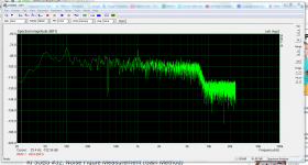
You know that -120 dB is one part in a million, yes? Your noise problem is a million times weaker than the signal...that means there really is no problem!
With the scale corrected the peaks of the bumps are at around -100dB. In some graphs the Y values are not correct.
If they were really at -120 i would agree.
And this unit has that potential just with a solution like one of these
http://www.amazon.com/s/ref=nb_sb_noss?url=search-alias=mi&field-keywords=Tascam+AC+Adapter+++
Packing things together can bring issues always.
Someone suggested in an earlier post on this thread that you use some copper foil to shield the divider (wall, bulkhead) between the SMPS and the rest of the circuitry. Why not give it a try, it seems an easy thing to try? (The foil must be grounded well.)
Yes. But the risk of a short circuit is quite real with everything exposed.
I would have done it immediately with some copper adhesive tapes.
There is a 400V cap in the smps. That is a bomb when charged.
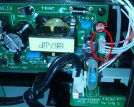
That grey four-pin connector is the power supply DC output, right?
I am attaching a picture with the output 4-wires connector. 2 wires are ground and the other 2 i guess V+.
So in the end is a single voltage out unit.
You can turn the power supply PCB over, and use a voltmeter to measure the voltage at each of those four pins. (The black wire from the voltmeter needs to be grounded - you can clip it to the metal chassis, for example.)
The board must be on an insulating surface (wooden table top is fine). Obviously, no pets or small children around. Be careful to only touch the insulated handles on the voltmeter probes during the measurement, and stay away from the AC end of the board - there are dangerous voltages there.
If you like, you can also wear protective electricians (insulating, rubber) gloves, as an extra layer of safety.
(Google for "Class 00 electricians gloves" if you want more information.)
If you're not comfortable making the measurement, you may be able to find an electrician or electrical engineering student who will do it for you.
-Gnobuddy
Thanks a lot indeed ! i would buy absolutely a pair of this glove immediately.
The thickest one available
I think that with the glove i could try to measure it.
However there is already a value of
The original outputs 11.2 V, so 12 V ought to be fine
Tascam UH-7000 power supply noise
If i think that just a humble Seasonic SSA-0601S-1 would give something like this ...
An externally hosted image should be here but it was not working when we last tested it.
Y axis is not correct by the way. A -120/130 dB noise base line could be more realistic.
This unit has a big potential for high-end. Because the AD and DA converters on board seem really top notch.
Thanks a lot again, gino
Attachments

Last edited:
ginetto61,
Just curious, would you say it's possible to "fix" something when you have no way of telling whether it's broken or fixed?
Bear with me for a moment here. Let's say there was some words printed on piece of paper. Words printed by a machine that can print incredibly small things. So small it's not possible to see these words with your eyes. Now someone tells you there may be a spelling mistake in those words. Do you believe you could correct that spelling mistake? If you don't own a microscope how would you determine whether you corrected the mistake or made a bigger mistake by trying?
The noise on your circuit is both outside the frequency range humans can hear and at level so low you wouldn't be able to hear anything even if was inside our hearing range, so it is in multiple ways invisible to you just like the tiny printing example. You have no way of telling whether it's there or gone, certainly not by using your ears, so how could you ever know that you've "fixed" it?
Hi you know what is the problem ? that in my mind is not acceptable that an external smps costing some 30-40 USD would have provided better performance.
Even the exact same one !!! just placed in an external box.
To be perfectly honest i do not like at all how this interface is built.
I would much prefer something slimmer and wider like almost all the interface.
It is a little like making a wonderful portrait of a nice woman and then painting a pair of thin black moustache on her face .. this is what is it.
Thansk again, gino
Last edited:
I posted a link to dipoles for dummies on the other thread, this is important because CABLES act as antennas and can be the cause of emissions increasing...
As to shielding again there is more to it than you may think and incorrect shielding can again cause certain emissions to rise....
As to shielding again there is more to it than you may think and incorrect shielding can again cause certain emissions to rise....
I posted a link to dipoles for dummies on the other thread, this is important because CABLES act as antennas and can be the cause of emissions increasing...
Hi and thanks again do you refer to these ones ?
Your EMC starter...
http://www.hottconsultants.com/pdf_files/dipoles-1.pdf
http://www.hottconsultants.com/pdf_files/dipoles-2.PDF
http://www.hottconsultants.com/pdf_files/dipoles-3.PDF
Add Ralph Morrison to your list of required reading...
Amazon.co.uk: Ralph Morrison: Books, Biogs, Audiobooks, Discussions
The fields of electronics is a good starter....
I have as I said previously been learning about EMC from a practical (and academic)viewpoint for 30+ years, don't expect enlightenment overnight... The practical side is doing layouts and EVERY layout I do being tested quite often to the extreme for EMC, a lot of the stuff I play with has far tighter requirements than consumer products...
As to shielding again there is more to it than you may think and incorrect shielding can again cause certain emissions to rise....
My point is that even for issues very very far from trivial, still a very trivial solution can work
Just extracting the original power supply from the case solve the issue completely. Not partially ... 100% !
Or just putting a piece of wire inside and dc socket on the back would allow for the use of a decent linear or switching ps.
Do not focus the absolute values on the Y axis ... they are not correct.
Are you willing to accept a bump of 30-40 dB in noise ? if this bump can be very easily eliminate.
My understanding is that to avoid the external adapter they have introduce the noise.
I would have cured a little better both cables routing and smps shielding.
The more i think about it the more i am convinced that an external power supply, used for other similar equipment by the same manufacturer, is the solution. Just a decent external smps would remove completely the bumps.
And it is what i am going to do 100% sure.
The problem is just practical. The wires are very thin and i have to check the Vout correctly as soon as a i will receive the isolating gloves.
And i am not decided about just putting a wire inside, or add some uF or even a complete DC-DC regulation stage and use an external ps slightly higher in voltage.
Thanks again, gino
Hi Guys !
thanks a lot again for the very kind and valuable support.
In the meantime i have found a huge discovery ... the ARTA software
You can see my request for support here
http://www.diyaudio.com/forums/soft...measurements-arta-_-tutorial.html#post4720735
It provides a spectrum analyzer function that i have tested on my usb headset of which i am attaching the spectrum (my 1st spectrum ever !)
Of course next i will try some usb interface to see how silent they are.
Then maybe in the future some distortion measurement.
It looks like a really great SW indeed.
I am very excited.
Kind regards, gino
Attachments
Why not move the SMPS outside, then? All you need is to find or make a suitable adaptor cable: a four-wire cable with a 4-pin male header on one end to plug into the SMPS (grey) cable, a 4-pin female header on the other end to plug into the original header where the SMPS cable now goes.Hi you know what is the problem ? that in my mind is not acceptable that an external smps costing some 30-40 USD would have provided better performance.
Even the exact same one !!! just placed in an external box.
You have already removed your SMPS from the chassis, so just extend the wires as described above, and you have what you want...and, it's an easily reversible modification if you do it the way I suggested.
(By the way: -100 dB is still one hundred thousand times lower than 0 dB. I guarantee you do not have 100 dB of signal to noise ratio in your recording studio. If your loudest sound is, say, 90 dB SPL, and the background noise level is 30 dB, you only have 60 dB dynamic range. The tiny, out-of-audio-band, noise in your TEAC is still a hundred times lower than the background noise.)
-Gnobuddy
Why not move the SMPS outside, then?
Hi again ! yes ! this is exactly my idea.
But after seeing that 400V cap i am a little scared by open frame smps.
They are like bomb ... to do this i also should find a suitable box for the smps.
All you need is to find or make a suitable adaptor cable: a four-wire cable with a 4-pin male header on one end to plug into the SMPS (grey) cable, a 4-pin female header on the other end to plug into the original header where the SMPS cable now goes.
It is here that i am lost. I have looked on ebay and there are thousands of different types.
The grey cable you see it is a signal cable going to the headphone out.
Actually this i find quite weird. The headphone out on the pcb is completely opposite of the headphone out on the front of the unit.
Then there is this long grey cable running through all the unit and i am pretty sure it is not shielded. What a nice antenna for noise ...
However ... i am getting a little mad because the 1st thing i would take care of is to separate power supply from the circuits .. at least with a shielding partition or even in two separate boxes connected with an umbilical.
To be more clear, the smps has just one AC in and one DC out (4 wires cable with one wire red and 3 white, but they are connected 2 by 2 so in the end it is a single voltage supply ... it should be 11.2 VDC from what i read). I am attaching a picture of the output 4 wires cable.
You have already removed your SMPS from the chassis, so just extend the wires as described above, and you have what you want...and, it's an easily reversible modification if you do it the way I suggested.
(By the way: -100 dB is still one hundred thousand times lower than 0 dB. I guarantee you do not have 100 dB of signal to noise ratio in your recording studio. If your loudest sound is, say, 90 dB SPL, and the background noise level is 30 dB, you only have 60 dB dynamic range.
The tiny, out-of-audio-band, noise in your TEAC is still a hundred times lower than the background noise.)
-Gnobuddy
yes i agree but if i can eliminate also those bumps i would be happier.
However i would be more comfortable with using a new and enclosed power supply and place a new dc socket on the back of the unit like i understand also Tascam has done for other models.
At the point the external dc ps could be everything of decent quality, even a linear one.
Instead for smps some good brands are Seasonic and MeanWell.
At the point this interface should really be dead silent. Hopefully.
Thanks a lot again, gino
Attachments
Hi Guys!
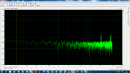
yes the noise is there ....
The sad thing is that the basic line is down to -140dB (!)
If i think that just an external ac adapter could have erased those nasty peaks ...
it will take some time .. but one day those peaks will go away for sure.
Kind regards, gino
yes the noise is there ....
The sad thing is that the basic line is down to -140dB (!)
If i think that just an external ac adapter could have erased those nasty peaks ...
it will take some time .. but one day those peaks will go away for sure.
Kind regards, gino
Attachments
Last edited:
Hi again !
i have studied more the issue.
I have come to the conclusion that the solution of putting a smps in the same box of sensitive audio digital circuitry is very challenging and often when shielding is not cured enough really a recipe for disaster.
These things spit EMI/RFI all over the place.
I think that in the end the smartest move will be to remove the internal smps and use instead and external power supply, even a smps but encapsulated. Actually this is the much more common solution adopted by other manufacturers and what i will do for sure.
The problem maybe now is to select/build a decent AC adapter.
But i am pretty sure that almost any will give better noise performance than the present solution.
I will post the graph with the external power supply.
Thanks a lot again for you very kind and valuable technical support.
Have a nice day !
Kind regards, gino
Why not take out the existing power supply (you've already done that), put it in a separate box, and extend the four-wire power cable? Surely that's easier than coming up with an entirely new power supply?I think that in the end the smartest move will be to remove the internal smps and use instead and external power supply, even a smps but encapsulated.
-Gnobuddy
a recipe for disaster.
These things spit EMI/RFI all over the place.
are you sure you know how to buy a good one or even measure it? consider this https://www.youtube.com/watch?v=BFLZm4LbzQU
- Status
- This old topic is closed. If you want to reopen this topic, contact a moderator using the "Report Post" button.
- Home
- Amplifiers
- Power Supplies
- SMPS _ shielding options.