Thank you very much!
The test point wasn't explained at all. I've been testing at the plates
also.
Now I can carry on.
Glenn
What component types have you used? The capacitors you use to bypass the supply make a big difference!
Just a reminder remember at power on and off the thump in the headphones is loud! I fitted a delay headphones on and headphones off then power off.
Regards
M. Gregg
Last edited:
I'm using a linear home brew power supply, so bypass caps are on that, not sure what you mean. I've actually got an issue with my power supply right now. The LM317 regulator shuts down after 5-10 seconds, and its really hot even with the heat-sink. The transformer is rated for 2 amps at 34v, and the LM317 is rated for 1.5 amps, so I have to dig into it a little more. Thanks for the help
Glenn
Edit: Here's the power supply I'm using
ftp://webpages.charter.net/tubeamp/12.6vdc%20power%20supply.jpg
Glenn
Edit: Here's the power supply I'm using
ftp://webpages.charter.net/tubeamp/12.6vdc%20power%20supply.jpg
Last edited:
Sorry, the link to the schematic is at:
http://webpages.charter.net/porkchop/tubeamp/12.6vdc%20power%20supply.jpg
Forget to take off the "ftp"")
http://webpages.charter.net/porkchop/tubeamp/12.6vdc%20power%20supply.jpg
Forget to take off the "ftp"
I think I found the problem with the power supply. I'm running 36vdc into the 317 regulator, and getting 12vdc out. This give me 24v differential, which limits the current available to just under 1A. Now I measured the current going to the amp at 381mA, but it may just take more when the cathodes of the 12AU7 are cold, plus I'm running an LED on the power supply for a pilot lamp (not much current but it's another thing to add). I'm using a 24v transformer now, so I'm going to try and go to a 12v transformer, this should give me around 18v after rectification. Using this should give me around a 6v differential (18v-12v) over the regulator and allow me to get the full 1.5A current.
Does this sound reasonable?
Glenn
Does this sound reasonable?
Glenn
Just for interest!
If you take the voltage drop across the regulator and multiply it by current in Amps "taken by the amp", you can see how much wattage you are dissipating. You may have to create a soft start for the heater on the ECC82, because it is nearly short circuit at start up! You need to get the input voltage as low as possible to reduce the voltage drop across the regulator, however you still need to get regulation! Try a high wattage resistor in front of the Reg, this would give a soft start. However the voltage would drop based upon current drawn.
The modification you suggest is much better than the 36V.
You need to add up all the current demands and look at how much current the reg can take. I run an Lm7812 on my amp and the heat sink runs quite hot.
I have 2 relays a timer 2 LED's + the ECC82 running with Approx 18V DC in! It is on a heat sink a picture is in post 21 of this thread!
You could use your output delay to "switch out" a low value resistor in series with the ECC82 heater! Or have two switches power and output.
The bypass caps are small film caps across your smoothing capacitors. If you are using some other supply then the small bypass caps are after the regulator value I used are 0.1uF and 0.01uF poly prop.
Regards
M. Gregg
Last edited:
Okay, (32v-12.6v)*.381A=8.91 Watts, doesn't seem too high for the LM317.
I thought that the issue might be the cold cathode hogging the current at start-up. I like the idea of having a current limiting resistor in the heater string.
Thanks for all the suggestions, I'll keep you posted.
Glenn
I thought that the issue might be the cold cathode hogging the current at start-up. I like the idea of having a current limiting resistor in the heater string.
Thanks for all the suggestions, I'll keep you posted.
Glenn
Okay, (32v-12.6v)*.381A=8.91 Watts, doesn't seem too high for the LM317.
I thought that the issue might be the cold cathode hogging the current at start-up. I like the idea of having a current limiting resistor in the heater string.
Thanks for all the suggestions, I'll keep you posted.
Glenn
If you think of the size of a 10Watt resistor it is quite alot of power on the small LM317 tab!
These problems are what I found so interesting when building this project. They are small I know, however they are fun to solve.
Last edited:
Plus looking at the chart for the 317, if my input-output differential is 24v, I only get a little under 1A for output current. I think I'll change the transformer to the 12v one I have, should give me around 18v after rectification. At least it will give me more current to work with.
Yes I agree it's fun solving little problems like this, that's how I learn the best anyway.
Thanks again.
Yes I agree it's fun solving little problems like this, that's how I learn the best anyway.
Thanks again.
After switching to a 12.6v transformer I get 3.3 watts over the LM317, much cooler running and it doesn't shut off due to thermal overload.
I guess my only question now is can I use only one side of the transformer? It's a 12.6v-0-12.6v (center tap) and I'm only using 1/2 of the secondary winding, is this acceptable?
Thanks MG for all the help!
Glenn
I guess my only question now is can I use only one side of the transformer? It's a 12.6v-0-12.6v (center tap) and I'm only using 1/2 of the secondary winding, is this acceptable?
Thanks MG for all the help!
Glenn
I'd use both halves of the winding, making a fullwave centertapped PSU. You have a bridge on it now, but only on half the secondary, correct? If so, wire it like this:
Just ground the center tap.
An externally hosted image should be here but it was not working when we last tested it.
Just ground the center tap.
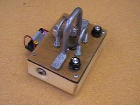
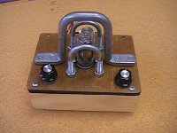
Speaking of the ValveCaster
Hello: Pardon the reference to an earlier bit of the thread. Here's the case around the Matsumin ValveCaster I just did over the weekend. The only other tube project I ever did that worked was the Real Mctube a few years ago: this one was fun and quick and it's all point-to-point hanging off the bottom of the tube socket...the tube guards are u-bolts and a phone company cable guide I found in my junk box. Painted inside with black shielding stuff I use in guitar cavities. It works, the sound is okay from clean to slightly dirty, and yes, it's limited, but for guitar, anything that's a little different is useful (like sticking a tiny speaker at the end of a plastic tube and mic'ing the other end just to find out what it sounds like). Expecting that it will eat batteries, I just hung a clip right off the outside for convenience. No artwork or "in" and "out" yet...it's cleaner without fake model names and all that anyway.
Hello: Pardon the reference to an earlier bit of the thread. Here's the case around the Matsumin ValveCaster I just did over the weekend. The only other tube project I ever did that worked was the Real Mctube a few years ago: this one was fun and quick and it's all point-to-point hanging off the bottom of the tube socket...the tube guards are u-bolts and a phone company cable guide I found in my junk box. Painted inside with black shielding stuff I use in guitar cavities. It works, the sound is okay from clean to slightly dirty, and yes, it's limited, but for guitar, anything that's a little different is useful (like sticking a tiny speaker at the end of a plastic tube and mic'ing the other end just to find out what it sounds like). Expecting that it will eat batteries, I just hung a clip right off the outside for convenience. No artwork or "in" and "out" yet...it's cleaner without fake model names and all that anyway.
Attachments
Last edited:
I'd use both halves of the winding, making a fullwave centertapped PSU. You have a bridge on it now, but only on half the secondary, correct? If so, wire it like this:
An externally hosted image should be here but it was not working when we last tested it.
Just ground the center tap.
Thanks! does this still give me 1/2 the output voltage rating of the tranny like I have now? And yes, I have a bridge on only one half of the secondary, using from the center tap to one side of the secondary winding. For future reference, is it kosher to use only one half of the secondary winding?
Glenn
Yup, still only rectifies 12.6 volts for you.
As for Kosher, I've always been told that it leaves the other half unused, the center tapped is a bit more efficient than just using half. It heats both halves alternately, rather than one half all the time. The center tap version has two fewer diodes in the signal path, that's always good right?
As for Kosher, I've always been told that it leaves the other half unused, the center tapped is a bit more efficient than just using half. It heats both halves alternately, rather than one half all the time. The center tap version has two fewer diodes in the signal path, that's always good right?
I think you are at a point where you need to take stock of what you intend to do with the project!
Regards
Power supply: You need to work out if you are going to supply the power amp section from the same supply. If you are then you need to find out if one half of the supply transformer has enough current to drive the tube section and the other half the power section. Its easy to calculate from the VA of the Tx.
Or
Are you going to supply the whole thing from the full wave circuit shown with two regulators.
The first step is to test what you have now with a set of cheap headphones and Ipod or some input source and see how it sounds. (Don't put the head phones on and don't connect the headphones until the amp has warmed up) see if it is quiet then test! Then you can tweek the power supply set up as required! If all is O.K. then away you go again with the next step! This tube amp lets everything through including PSU noise! So you may have to play with the PSU to get it working O.K.
You will need a volume control on the input!
Sorry about the bold text just thinking about your ears and noise!
Regards
M. Gregg
Regards
Power supply: You need to work out if you are going to supply the power amp section from the same supply. If you are then you need to find out if one half of the supply transformer has enough current to drive the tube section and the other half the power section. Its easy to calculate from the VA of the Tx.
Or
Are you going to supply the whole thing from the full wave circuit shown with two regulators.
The first step is to test what you have now with a set of cheap headphones and Ipod or some input source and see how it sounds. (Don't put the head phones on and don't connect the headphones until the amp has warmed up) see if it is quiet then test! Then you can tweek the power supply set up as required! If all is O.K. then away you go again with the next step! This tube amp lets everything through including PSU noise! So you may have to play with the PSU to get it working O.K.
You will need a volume control on the input!
Sorry about the bold text just thinking about your ears and noise!
Regards
M. Gregg
Yup, still only rectifies 12.6 volts for you.
As for Kosher, I've always been told that it leaves the other half unused, the center tapped is a bit more efficient than just using half. It heats both halves alternately, rather than one half all the time. The center tap version has two fewer diodes in the signal path, that's always good right?
Lingwendil-
Okay, I'll give it a try! Thanks for posting the diagram. Something just didn't sit right with me using half of the winding, seems inefficient.
MG-
I am going to power everything from the same PS. The entire circuit draws 878mA, and it's a 2A transformer, so no big deal using half if I decide to keep it that way.
I did make note of the popping when switched on, so no headphones connected at turn-on, got it! I bought a ganged volume pot just for the build, so I'm good there. I'm very aware of the power supply noise getting into the circuit, this is my fourth tube amp I've built. That's actually why I built the linear supply, I was afraid of switching noise from a power brick.
Hopefully I'll be able to give it a test run tonight. I'm getting itchy to try it after all this build time
Thanks again everyone for all the help!
Glenn
Hello: Pardon the reference to an earlier bit of the thread. Here's the case around the Matsumin ValveCaster I just did over the weekend. The only other tube project I ever did that worked was the Real Mctube a few years ago: this one was fun and quick and it's all point-to-point hanging off the bottom of the tube socket...the tube guards are u-bolts and a phone company cable guide I found in my junk box. Painted inside with black shielding stuff I use in guitar cavities. It works, the sound is okay from clean to slightly dirty, and yes, it's limited, but for guitar, anything that's a little different is useful (like sticking a tiny speaker at the end of a plastic tube and mic'ing the other end just to find out what it sounds like). Expecting that it will eat batteries, I just hung a clip right off the outside for convenience. No artwork or "in" and "out" yet...it's cleaner without fake model names and all that anyway.
Oh man! Don't get me started on stomp boxes!
I love making pedals, I must have 6 or 7 that I home-brewed. That's what got me started on the whole tube amp building thing.
How's it sound?
Here's my homemade head and cab:
An externally hosted image should be here but it was not working when we last tested it.
I'm going to swap my avatar back to my Marshall cabinet simulator now.
Glenn
Last edited:
Can we see the inside of your amp head.
Looks very good!
I built a small fender champ gave it away last week to relative "player in need". So I just have my JCM600 now. Had a Jagstang for a while, loved it -the neck kept going out so I sold it on. Sorry off topic.
Regards
M. Gregg
Looks very good!
I built a small fender champ gave it away last week to relative "player in need". So I just have my JCM600 now. Had a Jagstang for a while, loved it -the neck kept going out so I sold it on. Sorry off topic.
Regards
M. Gregg
Sure, I'll have to dig them up as I don't have any "upskirts" loaded on the sever anymore. That amp is actually a "November" build from the AX84.com web site. It's only an EL84 PP amp, but I didn't need a real powerful amp for "Bedroom gigs" That being said, it's pretty loud in my opinion.
The JCM600 is a good head, nice sound. I really don't play that Danelectro much for the same reason, the neck is kind of wonky. I thought it looked kind of cool, especially after seeing Mr. Page use one My Les Paul sunburst is my main instrument, that neck never moves!
I'll post some inside pix as soon as I can.
Glenn
Apologies to everyone for the way-off topic, sorry
That being said, it's pretty loud in my opinion.The JCM600 is a good head, nice sound. I really don't play that Danelectro much for the same reason, the neck is kind of wonky. I thought it looked kind of cool, especially after seeing Mr. Page use one
My Les Paul sunburst is my main instrument, that neck never moves!I'll post some inside pix as soon as I can.
Glenn
Apologies to everyone for the way-off topic, sorry
- Status
- This old topic is closed. If you want to reopen this topic, contact a moderator using the "Report Post" button.
- Home
- Amplifiers
- Tubes / Valves
- Small Tube/SS hybrid amplifier design 9V