Soro,
Nice project!
Dovla,
Interesting link. I used this because I wanted to run the ECC82 from 12V DC. To see what happened!
Bigun,
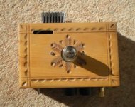
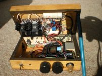
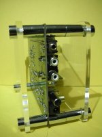
" Photo's of the inside"
It was done in a few hours so it's a bit of a birds nest!
Because it was in a wooden box I had to screen cables. I used PTFE silver plated cable as a twisted pair covered in foil with a drain wire twisted around the foil, covered with heat shrink!")
Regards
M. Gregg
Nice project!
Dovla,
Interesting link. I used this because I wanted to run the ECC82 from 12V DC. To see what happened!
Bigun,
" Photo's of the inside"
It was done in a few hours so it's a bit of a birds nest!
Because it was in a wooden box I had to screen cables. I used PTFE silver plated cable as a twisted pair covered in foil with a drain wire twisted around the foil, covered with heat shrink!
Regards
M. Gregg
Attachments
Have you considered abusing an op-amp or emitter follower
as a unity gain buffer to drive the grid in continuous A2?
Bootstrap plate load to increase both voltage and impedance.
Seriously look into capacitive charge pump doubler or tripler.
Also investigate boost switcher ICs for driving a string of LEDs.
as a unity gain buffer to drive the grid in continuous A2?
Bootstrap plate load to increase both voltage and impedance.
Seriously look into capacitive charge pump doubler or tripler.
Also investigate boost switcher ICs for driving a string of LEDs.
Member
Joined 2009
Paid Member
Bigun,
Because it was in a wooden box I had to screen cables. I used PTFE silver plated cable as a twisted pair covered in foil with a drain wire twisted around the foil, covered with heat shrink!
M. Gregg
It looks pretty dapper to me, nicely done !
p.s. my amp is also a bit of a birds nest, I'm the process of trying to tidy it up but I'm not sure its worth the trouble.
Have you considered abusing an op-amp or emitter follower
as a unity gain buffer to drive the grid in continuous A2?
Bootstrap plate load to increase both voltage and impedance.
Seriously look into capacitive charge pump doubler or tripler.
Also investigate boost switcher ICs for driving a string of LEDs.
Post a few circuits! LOL
A bit off topic:
I am building an Aikido pre using recom DC to DC for the heaters and inverter for the HT 450V with 350 V 60mA regulation at the moment. Also EM81 Vu meters. Run from 12V power supply. I will post this in another thread when complete!
Its an on going project!
Regards
M. Gregg
Last edited:
Post a few circuits! LOL
http://www.diyaudio.com/forums/tube...w-volt-fix-your-knowledge-10.html#post2302504
See Post#94 of that thread...
Last edited:
you can try this:
www.audiofaidate.org • Leggi argomento - PREcario (C) pre linea a batteria
he says:At 700mVrms distorsion is very low, close to the limit of measuring setup (0,03%)
V
www.audiofaidate.org • Leggi argomento - PREcario (C) pre linea a batteria
he says:At 700mVrms distorsion is very low, close to the limit of measuring setup (0,03%)
V
If you don't mind building a power supply, get a 12VAC transformer, stack a six stage voltage doubler on it, smooth it with a couple pi filters, and run your tube off that. This will get you a quiet, high enough voltage to make a high quality amp. Use a lm7812 for both your heater and the output stage. I did a lot with the lm386 in my beginnings, and honestly think their gain is too high to use a tube in front of them for hi-fi. I'd just build a Szekeres mosfet follower, and drive that with the tube, that's my favorite low-watt hybrid amplifier setup.
http://www.diyaudio.com/forums/tube...w-volt-fix-your-knowledge-10.html#post2302504
See Post#94 of that thread...
See post 95 I answered you
Sorry I didn't remember!Regards
M. Gregg
Thanks M Gregg
I use bettery supply B+ 12V
and sound is sweet.
now the tube is made for car use.
tube type is 6DJ8 .
my friend say the tube is use to fix BMW car stereo.
Soro,
Did you have any problems with vibration microphonics?
Where did you put it in the circuit " Car stereo"?
Soro,
Did you have any problems with vibration microphonics?
Where did you put it in the circuit " Car stereo"?
No it is not has any vibration microphonics.
sound is good and sweet.
you shall try it.
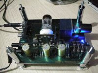
this is prototype.
it can use 6DJ8 6922 12AU7
(also 12AX7 but must change some thing)
more choose more fun
Attachments
Last edited:
No it is not has any vibration microphonics.
Effectively mounted in a car, while the car is running over normal road inperfections?
How about these $ 5 tubes?
http://www.mif.pg.gda.pl/homepages/frank/sheets/106/1/12AE7.pdf
Ok not 9V, but 12V is low enough..
http://www.mif.pg.gda.pl/homepages/frank/sheets/106/1/12AE7.pdf
Ok not 9V, but 12V is low enough..
Well, my build is coming along. I just completed the 12.6VDC linear power supply last night.
I've got the Vero board layout complete, and all the parts, so I'll start building this weekend. If any one wants the Vero board layout, I can post the link here.
Stay tuned for pictures. Thanks again everyone for the suggestions.
Glenn
Again, here's the circuit I'm building:NP-100v12: DIY 12AU7 (ECC82) Tube / IRF510 MOSFET Headphone Amplifier
Here's the Vero board layout: http://webpages.charter.net/porkchop/tubeamp/12AU7%20Headphone%20amp-%20Vero%20board%20layout.jpg
Last edited:
Okay, I've got it built and now we move into the troubleshooting phase
I'm using the 10k trim pot to try and set the voltage to 1/2 the power supply
voltage of 12.6vdc. I can only get down to 9.5v using the full 10k of the pot.
Now I can add a resistor in front of the pot to get me there, but it seems like
something isn't working correctly. The schematic says that you can use a 4.7k
resistor instead of the pot, but I set the pot to the 4.7k value before testing, and I was still getting around 12v. Seems like something isn't drawing enough current? Maybe the MOSFET?
Any ideas? Both channels are working the same, so I don't think it's a wiring issue.
Thanks
Glenn
Edit: Does this circuit need to be loaded on the output to work??
maybe that's the problem?
Last edited:
This may be of help from the forum;
1) In: Photograph 14: Setting the Bias "Adjust the two trim potentiometers to one-half of your supply voltage, 6 volts since we are using a 12v supply. "
Where should the 6v be tested for - at the junction of the FET Source and the LM317's 'IN'?
Heh - I've been testing AT the plate - only can get that down to about 9.2 volts or so... I'm guessing I'm testing in the wrong spot...
Yes, or at the postiive lead of your output electrolytic.
Link
NP-100v12 - 12AU7 / IRF510 HeadAmp Support Thread • DIY Audio Projects Forum
Regards
M. Gregg
- Status
- This old topic is closed. If you want to reopen this topic, contact a moderator using the "Report Post" button.
- Home
- Amplifiers
- Tubes / Valves
- Small Tube/SS hybrid amplifier design 9V