Deriving Xmax by subtracting the height of the voice coil winding from the height of the magnetic gap and dividing by 2 ignores magnetic and mechanical non-linearities and asymmetry, so has not been much in use since 1981, after which the measured approach started gaining traction. I can still remember when Mark Gander of JBL gave me a "top secret" paper about how to design ported cabinets using TS parameters back then...
Interesting that you mention JBL. Their old 1200GTi car audio sub (using a well-known JBL motor) had a rated Xmax of 8mm (based on the coil/gap approach) and a measured Xmax (10% THD) of 12mm. That's quite a difference.
It is a bit interesting though that B&C rates the driver as having a 6mm Xmax and the coil/gap approach gives a 3mm Xmax. that's a 100% increase and looks a bit... suspicious.
Chris, before committing to that subwoofer build, I suggest putting one of those drivers in a small sealed test box, run the Hornresp sim to see how much power you'd need to feed it to approach/exceed Xmax and do some REW THD tests. Or simply do the same thing using close-miked measurement of the driver in free air. That should give you a pretty good idea of how much power it could be fed before exceeding 10% THD, and that in turn can be used to work out its effective Xmax from the corresponding Hornresp sim.
ICG,
B&C told no lies about winding height, plate thickness or Xmax and Xvar.
If you want to believe the B&C 6ps38 Xmax is "wrong", you'll also have to throw out all the rest of their (and most everyone else's) woofer's Xmax ratings.
Deriving Xmax by subtracting the height of the voice coil winding from the height of the magnetic gap and dividing by 2 ignores magnetic and mechanical non-linearities and asymmetry, so has not been much in use since 1981, after which the measured approach started gaining traction. I can still remember when Mark Gander of JBL gave me a "top secret" paper about how to design ported cabinets using TS parameters back then...
B&C does provides Winding Depth and Magnetic Gap Depth on their spec sheets, but Xmax is not derived from those numbers, it is measured according to the AES2-1984 standard, corresponding to a maximum of 10% total harmonic distortion (THD) with a sinusoidal signal.
The “Xvar” value reported by B&C is measured as when the magnetic field seen by the voice coil, or the total suspension compliance, or both, drops to less than 50% of their small signal value.
Xvar can be more, less or equal to Xmax.
Art
You are missing the whole point. You need to understand this as it is crucial for any discussion. B&C did not lie. They said 6mm Xmax. That's the absolute excursion, or in other words, peak-to-peak. That makes it 3mm to each side. You can add x% to it if you want but that does not add up to +/-6mm in any possible way. The simulation relies on said +/-6mm (or even 7,5mm) while the driver does actually only do the half of it!
Yes, definitions are crucial for any discussion, and you are mistaken. I made the same mistake years ago- no bull!You are missing the whole point. You need to understand this as it is crucial for any discussion. B&C did not lie. They said 6mm Xmax. That's the absolute excursion, or in other words, peak-to-peak. That makes it 3mm to each side. You can add x% to it if you want but that does not add up to +/-6mm in any possible way. The simulation relies on said +/-6mm (or even 7,5mm) while the driver does actually only do the half of it!
Xmax is by definition one way excursion, not peak to peak, a 6mm Xmax is a peak to peak excursion of 12mm total. You can measure excursion by placing a white dot near the edge of a cone, persistence of vision makes the movement easy to track.
Mechanical limitations of drivers are often quoted peak to peak ("travel"), though Xmech, or Xlim are also one way measurements.
Most modern PA woofers have Xlim around twice Xmax, and usually the suspension, rather than the coil smashing the back plate is the limitation.
Cheers,
Art
Xmax is by definition one way excursion, not peak to peak
This is my understanding also. It is the definition used in Hornresp.
Attachments
Xmax is by definition one way excursion, not peak to peak, a 6mm Xmax is a peak to peak excursion of 12mm total. You can measure excursion by placing a white dot near the edge of a cone, persistence of vision makes the movement easy to track.
Mechanical limitations of drivers are often quoted peak to peak ("travel"), though Xmech, or Xlim are also one way measurements.
Most modern PA woofers have Xlim around twice Xmax, and usually the suspension, rather than the coil smashing the back plate is the limitation.
Yes, usually it's one side excursion. And to my understanding it should always be that way. But by no means that's the definition, it can be both, if you don't specify it. In my opinion these values should always have the +/- or p-p notification to be absolutely clear. There are manufacturers who give the p-p value like Seas (PDF) but also say it's peak to peak. B&C does not say p-p but they do not say +/- either. If you are unsure, calculate it yourself.
Now just look at the datasheet and calculate the Xmax yourself, as I said, be generous if you want and add x% to it. Please tell then how you come from the mathematically 3mm to 6mm or even 7,5mm.
This is my understanding also. It is the definition used in Hornresp.
Yes, it's mine too and that's what got me in the first place. I only noticed it when I was looking for the winding height and realized "uh, that's odd, that can't be right". And yes, that's how hornresp and most other programs do it. That's why you have to check for how the Xmax value is calculated.
1) I agree, Xmax is and should be one way excursion- it can't be both peak to peak and one way, and if not specified should be assumed to be the standard definition.1)Yes, usually it's one side excursion. And to my understanding it should always be that way. But by no means that's the definition, it can be both, if you don't specify it.
2)In my opinion these values should always have the +/- or p-p notification to be absolutely clear. There are manufacturers who give the p-p value like Seas (PDF) but also say it's peak to peak.
3)B&C does not say p-p but they do not say +/- either. If you are unsure, calculate it yourself.
4)Now just look at the datasheet and calculate the Xmax yourself, as I said, be generous if you want and add x% to it. Please tell then how you come from the mathematically 3mm to 6mm or even 7,5mm.
2) Though your example of Seas is clear in this discussion, others not noticing or understanding "(p-p)" may assume the driver to have double the Xmax and Xmech it actually has- the numbers must be divided by 2 to use in Hornresp.
3) B&C is inconsistent in their spec sheet nomenclature, some include +/- in front of the Xmax and Xvar numbers, others don't. Some use commas (,) rather than periods(.) which can throw USA folks.
4) I have done the mechanical derivation of the 6ps38 as well as many other B&C drivers, and it is obvious that in no case do they use the 1981 era mechanical derivation to determine Xmax, it is measured according to the AES2-1984 standard, corresponding to a maximum of 10% total harmonic distortion (THD) with a sinusoidal signal.
Having not personally tested the 6ps38 I would not swear the spec sheet is not mistaken, but the fact that the Xmax happens to be double what the mechanical derivation is could simply be coincidental.
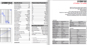
As examples, the B&C 21SW152-4 would have a mechanically derived Xmax of only 9mm, while it's specifications are 15mm Xmax and 16mm Xvar, nearly double.
The B&C 21SW115-8 would have a mechanically derived Xmax of 10mm, but is rated for 14mm Xmax and 16mm Xvar.
Obvious from the measured results, there is more to Xmax than the "easy math" would suggest.
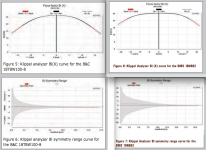
B&C (and no doubt other manufacturers) use coil winding formats that were not employed 37 years ago when Mark Gander suggested the mechanical derivation for Xmax.
Klipple analyzers were not available then, they have been instrumental to design practices that have increased linear excursion to far more than typical four decades ago.
At any rate, like Jimi sang back in those days: “if a 6 turns out a 9, I don’t mind” ;^)
Cheers,
Art
Attachments
Last edited:
I love how the OP is arguing the 6.5" driver should be assessed by xvar, yet measures it against known high performing sub drivers based on their xmax rated in the traditional sense.
Go look at videos on lab drivers and how much excursion they can run without any real distortion. Then also consider even IMAX theatres use lab 12 drivers at high SPL and excursion down to 20hz.
I do like the idea of this little sub design but the numbers are pretty low for PA work.
The obsession with 40hz extension is actually probably the biggest problem. A tiny system doesn't need 40hz so if anything DON'T equalise down the rise, use it as an artificial bass boost(kick drums will focus energy right where your power dip issues are)
If anything, tune higher for better power handling and go for 50hz. You'll be surprised that most program material (and in your own words for a quiet sitting church type scenario) would have almost no meaningful content you would actually need to reproduce.
Getting say 3db more from a higher tuned design would be far more useful, especially with less of a power dip/excursion problem at 60-70hz. Your design is already using xvar which is at the point of audible distortion so you have NOTHING in reserve at frequencies where most kick drums will be centred.
Commercial PA gear often has excursion minima at those frequencies ON PURPOSE!
The obsession with 40hz extension is actually probably the biggest problem. A tiny system doesn't need 40hz so if anything DON'T equalise down the rise, use it as an artificial bass boost(kick drums will focus energy right where your power dip issues are)
If anything, tune higher for better power handling and go for 50hz. You'll be surprised that most program material (and in your own words for a quiet sitting church type scenario) would have almost no meaningful content you would actually need to reproduce.
I agree with this. My POC6 is tuned to 48 Hz, and I use a boost @50 and cut @ 30 Hz and 20 Hz to kill everything below that while preserving the passband. I was pleasantly surprised that the result was quite acceptable.
@weltersys: Yes, I found the same inconsistency. There are also other manufacturers who changed the way they specified and calculated their Xmax. Sometimes it's just the change of the method, in other cases I got somehow the impression they are using it as a way to sell off otherwise less desireable drivers. I don't know which is the case at B&C but I think they do not need that to sell their drivers since they produce good quality. Nevertheless, if you use a driver outside its working parameters, the performance virtually (and often even literally) crashes.
I strongly urge everyone to check the values and don't rely on advertised specs especally at the Xmax, always calculate it yourself and only compare the mathematical excursion
(winding height - pole plate thickness)/2
even if in praxis you can use more than that.
@Lunchietey: Yes, I totally agree. They can work fine at a higher tuning and often it's not needed at all to go down to 40 Hz. But if the 40 Hz are a must, for the love of god, use different drivers, these will perform horribly. Sell them, build tops or not-that-deep-tuned-subs, build a mini-line-array, whatever, but please, please don't use them that far outside of their specs.
So, I gave up and decided to test a driver for myself.
20Hz sine tone, free air, turn it up until you can tell the driver is reaching some limits. You get around 8mm p/p when something starts to go non-linear, and it won't go much further than 11mm.
Looks like these drivers don't share the 6PS38's Xmax/Xvar, and I was wrong to assume they did.
Altering the sims, I can get 118dB down to 65Hz, -3dB at 60Hz, from that cabinet with a 60Hz tuning, and less than 20v drive voltage.
With a JBL GTO1214 (sim'd because I happen to have a pair of them around) in the same size box, I can get 120dB from 40Hz upwards with 50v input (600w, so only good for peaks as the motor won't take that indefinitely), and it's excursion-safe even at that level. EDIT - that works until you enable "Lossy Le", which certainly applies to that driver. At that point, the response gets quite peaky and efficiency drops by around 2dB.
Guess it's time to start a new thread. Sorry for wasting everyone's time - I thought the 6" drivers had the same mechanical parameters as the ones they're based on, but that wasn't the case by a long shot.
Chris
Last edited:
20Hz sine tone, free air, turn it up until you can tell the driver is reaching some limits. You get around 8mm p/p when something starts to go non-linear, and it won't go much further than 11mm.
Did you measure distortion?
Did you measure distortion?
Distortion would've been exceptionally high, since I was running the driver free-air - 20Hz output would've been around 10dB, while the audible distortion components were around 50dB.
Loaded into a box, things would be quite different. However, the cone would still have reached its limits at a similar excursion level. Measuring reliably at low frequencies is quite difficult unless you set everything up outdoors. For a very quick test, knocking up an enclosure and testing it outdoors would be too much work.
I'm going to play around with simulations and see if I can come up with something worthwhile, whether it's using these drivers or some others. The 6.5" main PA speakers are still going ahead, but for now I'll just use the 15" subs.
Chris
So, I gave up and decided to test a driver for myself.
20Hz sine tone, free air, turn it up until you can tell the driver is reaching some limits. You get around 8mm p/p when something starts to go non-linear, and it won't go much further than 11mm.
Looks like these drivers don't share the 6PS38's Xmax/Xvar, and I was wrong to assume they did.
The 6PS38 actually do not have +/-6 mm Xmax. But I'm relieved you've tested it yourself, you've been quite above the Xvar. Like globalplayer said, a distortion measurement would have shown you that.
Altering the sims, I can get 118dB down to 65Hz, -3dB at 60Hz, from that cabinet with a 60Hz tuning, and less than 20v drive voltage.
That sounds reasonable for these drivers. Are you happy with that? Is that deep enough? I'm afraid it's not satisfactory though.
With a JBL GTO1214 (sim'd because I happen to have a pair of them around) in the same size box, I can get 120dB from 40Hz upwards with 50v input (600w, so only good for peaks as the motor won't take that indefinitely), and it's excursion-safe even at that level. EDIT - that works until you enable "Lossy Le", which certainly applies to that driver. At that point, the response gets quite peaky and efficiency drops by around 2dB.
That sounds reasonable too. The 2dB drop is the power compression and to be expected to hit there. That means it quickly gets to the point of dimishing returns of more and more power. If your music material got a low crest factor, it can be a lower loss.
Guess it's time to start a new thread. Sorry for wasting everyone's time - I thought the 6" drivers had the same mechanical parameters as the ones they're based on, but that wasn't the case by a long shot.
See, I prevented the waste of resources, material and disappointment and I do not find that a waste of time.
The 6PS38 actually do not have +/-6 mm Xmax. But I'm relieved you've tested it yourself, you've been quite above the Xvar. Like globalplayer said, a distortion measurement would have shown you that.
Goodness me.
These drivers are not the same as the 6PS38. They use a cone, basket and surround that are similar in appearance, but they are NOT the same driver. The 6PS38 may well have 6mm of one-way Xmax - I don't know, I haven't tested it.
The 2dB loss you're talking about isn't power compression. It's from the design of the motor itself, where drivers with long voice coils can show behaviour that's different to what the simple T/S parameters would suggest.
Power compression occurs due to heating at high power levels, and "Lossy Le" applies at all power levels.
Chris
Goodness me.
These drivers are not the same as the 6PS38. They use a cone, basket and surround that are similar in appearance, but they are NOT the same driver. The 6PS38 may well have 6mm of one-way Xmax - I don't know, I haven't tested it.
You do not need to test it, the datasheet already says so! You know, winding height and pole plate actually do say something..

The 2dB loss you're talking about isn't power compression. It's from the design of the motor itself, where drivers with long voice coils can show behaviour that's different to what the simple T/S parameters would suggest.
Power compression occurs due to heating at high power levels, and "Lossy Le" applies at all power levels.
You are right about the power compression. The 'Lossy Le' applies on all power levels but - who would have guessed that at a coil - where the inductance actually increases the impedance. And that is, for subwoofers, outside their used frequency range. As I afraid you'd despute that, please, just explain what it would be in your opinion and where informations about that can be found.
Chris: was it a 1/pi or 2/pi sim on the first post? Did not see the input data, might have missed it though.
ICG:
I get it you like basscad and winisd, but to call them more accurate than hornresp is just wrong. Akabak may be more accurate than hornresp, but only because you can input/calculate more data. Hornresp is a very good "medium", very accurate but still relatively easy to learn.
ICG:
I get it you like basscad and winisd, but to call them more accurate than hornresp is just wrong. Akabak may be more accurate than hornresp, but only because you can input/calculate more data. Hornresp is a very good "medium", very accurate but still relatively easy to learn.
ICG:
I get it you like basscad and winisd, but to call them more accurate than hornresp is just wrong.
That's not what I said. Read it again.
You do not need to test it, the datasheet already says so! You know, winding height and pole plate actually do say something..
You are right about the power compression. The 'Lossy Le' applies on all power levels but - who would have guessed that at a coil - where the inductance actually increases the impedance. And that is, for subwoofers, outside their used frequency range. As I afraid you'd despute that, please, just explain what it would be in your opinion and where informations about that can be found.
We do not know the dimensions of the magnetic structure in the drivers in front of me, so please stop talking about the 6PS38 like it still applies.
Simulating high inductance more accurately
The idea is that drivers with long coils and high inductance will behave differently to what might be expected from just the T/S parameters.
Chris: was it a 1/pi or 2/pi sim on the first post? Did not see the input data, might have missed it though.
2pi, groundplane.
I like to design with the worst-case in mind, so all of my main speakers are simulated in 4pi, and if they happen to give me a bit more because they're fairly close to the ground, that's a bonus.
Same for the subs - chances are they'll see some use near walls, but in a PA situation you can't rely on that.
Chris
Originally Posted by Brian Steele View Post
I don't think any simulation program will give good results if you enter the wrong values for the parameters..
While that's ofcourse true, BassCADe & co are still closer and hornresp might create the illusion of having something that would work.
Then please understand why I came to that conclusion, just like some others here. Will not quote the rest, in sum I still got the same impression.
You quote "experience" as a reason for not trusting/liking this software, and that may well be valid. But it would be of bigger benefit for the creator of the software: David McBean, myself and many others in this forum, to know in which specific cases you found it lacking. Please be constructive.
Edit:
Chris: I would argue the same is valid for domestic use as well.
Last edited:
- Status
- This old topic is closed. If you want to reopen this topic, contact a moderator using the "Report Post" button.
- Home
- Loudspeakers
- Subwoofers
- Small PA Subwoofer - 3x 6.5" drivers.