Currentflow,
That solution is exactly what I have been looking to do. I will be mounting the output devices perpendicular to the board surface and using an L shaped aluminum extrusion to attach the outputs to a rather narrow vertical finned heat sink. I only have a bit less than 4 1/2" max width on the heat sink and it must be even narrower than that as the edges of the heat sink create a seal to a self powered speaker.
That solution is exactly what I have been looking to do. I will be mounting the output devices perpendicular to the board surface and using an L shaped aluminum extrusion to attach the outputs to a rather narrow vertical finned heat sink. I only have a bit less than 4 1/2" max width on the heat sink and it must be even narrower than that as the edges of the heat sink create a seal to a self powered speaker.
didiet78: That's interesting, but still requires some intricate metalwork to accommodate two rows.
Kindhornman: I was thinking more on the lines of the Honey Badger, with the four outputs in a straight line, while keeping the drivers on a separate heatsink.
Kindhornman: I was thinking more on the lines of the Honey Badger, with the four outputs in a straight line, while keeping the drivers on a separate heatsink.
Last edited:
Currentflow,
I would think that would require some serious changes in the topology of the amp and output section. I think the original design by OS was supposed to be as symmetrical as possible and I don't know that you could get the same results moving all the devices to a single row?
I would think that would require some serious changes in the topology of the amp and output section. I think the original design by OS was supposed to be as symmetrical as possible and I don't know that you could get the same results moving all the devices to a single row?
Currentflow,
I would think that would require some serious changes in the topology of the amp and output section. I think the original design by OS was supposed to be as symmetrical as possible and I don't know that you could get the same results moving all the devices to a single row?
I agree it would lose its symmetry, but with some careful thought, bearing in mind that the peak currents would be somewhat lower with the baby version, I would imagine it should be achievable
") A traditional layout with L & R heatsinks of a lower height is really what I am looking for.
A traditional layout with L & R heatsinks of a lower height is really what I am looking for.Something like this ? Slewbaby with CFA-X BV Mod
For inline mounting, honey badger. OS prefer 2 line, something about shortest possible path
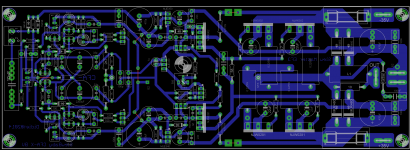
It may help may not, I did very similar setup on PCB (but different amp) and it is working really good. Small board can be mounted easly on the heatsing. pic bellow
Attachments
For Terry
Terry,
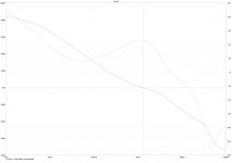
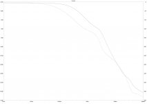
Have had a go at "improving" the circuit you posted earlier. There is a small change to the OPS but this can be removed if desired.
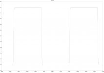
THD has improved significantly but slew rate is very low.
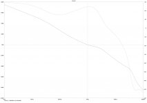
There is probably much room for tweaking but I like to get a circuit working with less than optimal perfromance. Then once its working in reality the performance can be pushed to the max. The simmed ULGF around 1MHz but I suspect you could push this up higher.
Clipping is ugly. But since there aren't any measures to deal with this it is not really a surprise.
C41, C42 are just place holders.
Stability 1 is the loop around OPS. Stability 2 is the main loop.
Let me know what you think...
Paul
P.S. I'm pretty certain this is less than optimal and other more experienced designers could improve it significantly. (I'm just a beginner)
Terry,
Have had a go at "improving" the circuit you posted earlier. There is a small change to the OPS but this can be removed if desired.
THD has improved significantly but slew rate is very low.
There is probably much room for tweaking but I like to get a circuit working with less than optimal perfromance. Then once its working in reality the performance can be pushed to the max. The simmed ULGF around 1MHz but I suspect you could push this up higher.
Clipping is ugly. But since there aren't any measures to deal with this it is not really a surprise.
C41, C42 are just place holders.
Stability 1 is the loop around OPS. Stability 2 is the main loop.
Let me know what you think...
Paul
P.S. I'm pretty certain this is less than optimal and other more experienced designers could improve it significantly. (I'm just a beginner
)Attachments
-
 AX-14 Slewmaster mcd1 sq wv.jpg128.8 KB · Views: 130
 -
 AX-14 Slewmaster mcd1 stability2.jpg173.4 KB · Views: 280
 -
 AX-14 Slewmaster mcd1 stability1.jpg178.9 KB · Views: 406
 -
 AX-14 Slewmaster mcd1 clg.jpg150.9 KB · Views: 464
 -
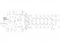 AX-14 Slewmaster mcd1 sch.jpg332 KB · Views: 499
 -
AX-14 Slewmaster mcd1.asc22 KB · Views: 67
Hmmmm, slew rate is slow and clipping is ugly. Doesn't sound like it belongs in this thread. Maybe not worth the trouble. I have a board stuffed but it in not working so I'm troube shooting that. I chew over and see. It can always just become another AX-14 if I can't get it working with the slewmaster.
I tried running it in LTspice. I don't now how to deal with the pulse thing. I hooked the sine wave back up so I could see. I have 3V at the input and it still isn't clipping so the gain must be lower now.
Thanks for all your work.
Blessings, Terry
I tried running it in LTspice. I don't now how to deal with the pulse thing. I hooked the sine wave back up so I could see. I have 3V at the input and it still isn't clipping so the gain must be lower now.
Thanks for all your work.
Blessings, Terry
Well you know me, I just can't stop myself.
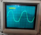
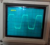
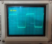
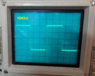
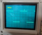
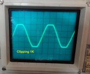
I got the issues worked out with the AX-14 frontend and hooked it up to my Baby Slewmaster OPS. No problems at all so far. Not a hint of oscillation. 6mv offset and this IPS doesn't have offset adjustment. The bias adjust perfectly. Pretty tickled. I have only played it through my test speakers so far but sounds lovely through those. After I made sure it plays music I hooked it up to the scope and sine wave generator and did some tests. Running at +-46V rails it clips at 25vac into an 8 ohm dummy load. Clipping looks really good at 1K. Symetrical and nice and flat on the top and bottom. Square waves show a hint of over shoot at 20K but up to there, very sharp. Gets a little rounded at 100K but I can't hear that high. I'm a little stoked that it seems to work so well. It is just built per the schematic I shared above. I did change the 2n5401 to KSA992A because I was out of them and changed the BC547/557 to BC456C/4556C for the same reason.
Blessings, Terry
Attachments
Well you know me, I just can't stop myself.
I got the issues worked out with the AX-14 frontend and hooked it up to my Baby Slewmaster OPS. No problems at all so far. Not a hint of oscillation. 6mv offset and this IPS doesn't have offset adjustment. The bias adjust perfectly. Pretty tickled. I have only played it through my test speakers so far but sounds lovely through those. After I made sure it plays music I hooked it up to the scope and sine wave generator and did some tests. Running at +-46V rails it clips at 25vac into an 8 ohm dummy load. Clipping looks really good at 1K. Symetrical and nice and flat on the top and bottom. Square waves show a hint of over shoot at 20K but up to there, very sharp. Gets a little rounded at 100K but I can't hear that high. I'm a little stoked that it seems to work so well. It is just built per the schematic I shared above. I did change the 2n5401 to KSA992A because I was out of them and changed the BC547/557 to BC456C/4556C for the same reason.
Blessings, Terry
Terry, this is very cool. Clipping with no sign of saturation or other artifacts, clean square response... Congratulations and greetings to Mile Slavcovic
Another great VFA front-end option

Cheers,
Valery
Nice work Terry, Since i was young I always liked Yamaha amplifiers, I was never wealthy enough to afford really expensive amplifiers. So when I first came across the APEX AX14 I just had to build one. I gave it with a set of speakers to my niece,
Regards
Hi Vostro,
Yes, the AX-14 sounds very nice. I have built three versions counting this one. Simple and common parts. Great for DIY.
So what's next? Anyone have a new IPS to try? How about that PSU circuit Valery? I'll be finishing up a TMG8 when the rest of my parts get here and then I'm going to need something to work on.
Protection
Hi Terry,
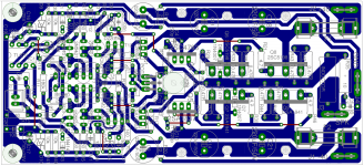
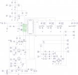
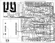
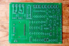
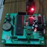
Here is the schematic, illustration of PCB layout and PCB photo of the latest version of protection module. If you like it, I can share gerbers. I will also give more details on standby transformer and relays used in the circuit, share the firmware and show how you can adjust the delays.
All indication is performed with a single LED - rather elegant, I think.
I am also working on the new hybrid front end - will give more info soon. It's got all the voltage gain performed purely by the tubes (2 x 12AU7) and rather light NFB - preserving the "tubish sound" - hopefully
Cheers,
Valery
Hi Vostro,
Yes, the AX-14 sounds very nice. I have built three versions counting this one. Simple and common parts. Great for DIY.
So what's next? Anyone have a new IPS to try? How about that PSU circuit Valery? I'll be finishing up a TMG8 when the rest of my parts get here and then I'm going to need something to work on.
Hi Terry,
Here is the schematic, illustration of PCB layout and PCB photo of the latest version of protection module. If you like it, I can share gerbers. I will also give more details on standby transformer and relays used in the circuit, share the firmware and show how you can adjust the delays.
All indication is performed with a single LED - rather elegant, I think.
I am also working on the new hybrid front end - will give more info soon. It's got all the voltage gain performed purely by the tubes (2 x 12AU7) and rather light NFB - preserving the "tubish sound" - hopefully
Cheers,
Valery
Attachments
I was planning on designing the same thing this weekend, but just plugging a UNO ic into the board. Nano works good too. No pulling parts to modify code.
Yep, that's a good thing about Nano - just connect mini-usb cable and upload an update... easy
Yep, that's a good thing about Nano - just connect mini-usb cable and upload an update... easy
My arduino using Atmega32A, but I do not have time to make amp protection soon
Attachments
Yep, that's a good thing about Nano - just connect mini-usb cable and upload an update... easy
That's a very neat solution. I have recently purchased an Arduino Nano for another project, which includes a mini-USB cable for only £4.99 (shipped from China) and couldn't fault it:
http://www.amazon.co.uk/ATmega328P-Module-Board-Arduino-Compatible/dp/B00H38Y3J6/ref=sr_1_4
- Home
- Amplifiers
- Solid State
- Slewmaster - CFA vs. VFA "Rumble"