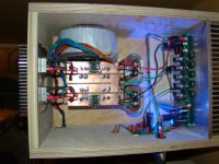
All 4 channels running, Now from everything but the subwoofer is slewmaster driven. Sounds very nice.
Could someone point me to how to raise or lower the gain using the cfa-x "H" ips? I need less gain on the mid/tweeter amps then on the woofer amps.
Thanks, Evan
Could someone point me to how to raise or lower the gain using the cfa-x "H" ips? I need less gain on the mid/tweeter amps then on the woofer amps.
Thanks, Evan
Attachments
Hi Evan,
The CFA-XH IPS gain is set by the ratio of the resistors R8 & R9 to R7 & R10, 2K7 and 100R respectively. Reducing both R8 and R9 will reduce the overall gain.
Would an attenuator or potentiometer at the input work for you? Do you know how much lower it actually needs to be? An attenuator type solution will give you fine adjustment without needing to modify the amplifier itself. Just something to think about.
If you really want to reduce the gain some take a look below:
Standard gain with R8 & R9 at 2K7 - Av is 28 (28.9dB)
Reduced gain with R8 & R9 at 2K4 - Av is 25 (28.0dB)
Reduced gain with R8 & R9 at 2K2 - Av is 23 (27.2dB)
Reduced gain with R8 & R9 at 2K - Av is 21 (26.4dB)
The CFA-XH will tolerate some gain adjustment without stability issues. As with anything just don't push things too far.
Jason,
An attenuator at the input would work but it is attractive to me to get the needed volume from the two sets of amps without adding more "stuff" to the chain. I'll know better when I have the house to myself and can bring the volume up to "11".
As it is the bass output is not at all far behind the mid/tweeters. The set sounds excellent. The highest frequencies sound amazingly clear.
Evan
I am pretty sure I simulated split NFB resistances as you described by inserting a resistor in the NFB line and that it did in fact work. I will re-run a sim on the topology (not the exact same amp) but I don't think there wouldn't be an issue. I'll report back a little later if that looks acceptable.
Perhaps I don't understand correctly but I would think that the change of the r7 and r10 resistors would give a very different final result than adding resistance to the NFB loop and reducing the correction of that part of the circuit? Though it may be easier to just add some resistance isn't that counter to what these designs are all about with lowest full bandwidth distortion numbers? What is the cost of 4 resistors in the scheme of thing here?
The cost of resistors is of course not a thought. I am thinking of making a small gain adjustment to a working set of amps adding one resistor in the NFB line is simply easier then either adding resistors to existing ones or unsoldering and resoldering to the board. That said I am admittedly unqualified to determine if the easy way is Ok. If it isn't ok then I'll take the time to do the correct job.
Evan
Evan
Just firing up 3 pairs of OPS and CFA-XH, things went well with no burning smell  .
.
Just a couple of questions about setting it up. I use 32AC which is about 45VDC rail.
I summarized my understanding below, Please verify if these are correct.
IPS
1) I measure across r13 and r14 (value of 3K9) in CFA-XH, it reads 30V which around 8ma. I should decrease r13, r14 so that the current is around 15mA.
2) Pot R5 and R12 in CFA-XH are for adjusting DC offset and CCS current, and the CCS can be read from R6 and R11 are these correct?
3) I adjust Pot R5 and R12 the same way as vssa. (one meter on SPK out and another one across R6 or R11 adjust so as too get desire CCS (which is 4-7ma?) and almost 0 DC offset.)
OPS
4) The OPS bias can be adjusted from pot r106 and can be read from 0.22R (emitter resistor). What is the appropriate bias current?
Thank
Chatchai
.Just a couple of questions about setting it up. I use 32AC which is about 45VDC rail.
I summarized my understanding below, Please verify if these are correct.
IPS
1) I measure across r13 and r14 (value of 3K9) in CFA-XH, it reads 30V which around 8ma. I should decrease r13, r14 so that the current is around 15mA.
2) Pot R5 and R12 in CFA-XH are for adjusting DC offset and CCS current, and the CCS can be read from R6 and R11 are these correct?
3) I adjust Pot R5 and R12 the same way as vssa. (one meter on SPK out and another one across R6 or R11 adjust so as too get desire CCS (which is 4-7ma?) and almost 0 DC offset.)
OPS
4) The OPS bias can be adjusted from pot r106 and can be read from 0.22R (emitter resistor). What is the appropriate bias current?
Thank
Chatchai
Last edited:
The 8mA for the shunt regulators is likely fine, though you can run them at a higher current if you like, understanding the resistor will run hotter. The CCS current can be verified across R6 and R11. Adjust it in a similar manner to the VSSA, monitor CCS current and offset. Set your OPS bias to give about 60mA per pair, measured across the 0R22 resistors.
Sounds like you are on track.
Sounds like you are on track.
The 8mA for the shunt regulators is likely fine, though you can run them at a higher current if you like, understanding the resistor will run hotter. The CCS current can be verified across R6 and R11. Adjust it in a similar manner to the VSSA, monitor CCS current and offset. Set your OPS bias to give about 60mA per pair, measured across the 0R22 resistors.
Sounds like you are on track.
Thank Jason
Regards
just bought slewmaster os and cfa boards. want to build high power mono blocks.
read though this post and don't any values for need toroidal trans.
what would a max rail limit should i avoid?
i would like to get 2 ordered right away
i want to have around 500 watts
i can order a 1000va 65-0-65
thanks
read though this post and don't any values for need toroidal trans.
what would a max rail limit should i avoid?
i would like to get 2 ordered right away
i want to have around 500 watts
i can order a 1000va 65-0-65
thanks
I know member still4given has used the Slews with some beefy power supplies, I believe right up to the +/-90V mark. In my opinion that is right at the maximum I would suggest anyone go. If you are targeting the 500W average power output mark then your choice of transformer should do it, assuming a nominal 8R load. I might suggest a smaller transformer that will give a softer 65 volt set of rails during initial testing before going for the full enchilada.
The power level you are targeting is serious business, work carefully, incrementally and triple test everything as you go.
The power level you are targeting is serious business, work carefully, incrementally and triple test everything as you go.
I know member still4given has used the Slews with some beefy power supplies, I believe right up to the +/-90V mark. In my opinion that is right at the maximum I would suggest anyone go. If you are targeting the 500W average power output mark then your choice of transformer should do it, assuming a nominal 8R load. I might suggest a smaller transformer that will give a softer 65 volt set of rails during initial testing before going for the full enchilada.
The power level you are targeting is serious business, work carefully, incrementally and triple test everything as you go.
thank you
first i am a novice here with little to none understand of this type of build.
open to any idea to just make the best ab amp i can build. not that i use 500w just thinking mega power in reserve where never 200w is used .
for me and others who look at slewmaster and are scared because we lack any notes or instructions what will the rail volts give in watts out?
like 30-0-30 will yeild x watts and 40-0-40 will yeild y watts and so on.
what can this amp give at 65-0-65?
also i understand danger in diy builds, i have built tube amps at 450volt
oh and thanks to still4given he sold me the boards. funny you mention him.
thanks jkuetemann for your thoughts
gordie
My amp is 63-0-63. It gives me 41VRMS into an 8 ohm dummy load which works out to 210 watts RMS if I'm doing the math correctly. 3.5VRMS drop through the amp
65VAC should give you around 91V rails which should work out to around 465 watts RMS into 8 ohms with the same 3.5VRMS drop.
I'm a fan of high power amps.I think the extra voltage brings out the detail in the highs better, but I think 500 watts is overkill. 250 watts will likely sound as good.
65VAC should give you around 91V rails which should work out to around 465 watts RMS into 8 ohms with the same 3.5VRMS drop.
I'm a fan of high power amps.I think the extra voltage brings out the detail in the highs better, but I think 500 watts is overkill. 250 watts will likely sound as good.
Hi Gordie,
Sounds like you might need a little primer on electronics calculations, feel free to correct me if I'm wrong and I don't wish to upset you if I'm going a little 'basic' on you.
First off, quoting an output power means little if you don't specify the nominal impedance of the load. When we are talking about audio that is usually either 4 or 8 ohms, so let's use 8 ohms for discussion.
Let's keep things really simple for starters and basically ignore losses for the moment. In reality, making decent estimations takes different variables and inefficiencies into account. The process might seem a little 'roundabout' but it gives opportunity to factor in the aforementioned inefficiencies in more realistic estimations.
You start off with a transformer that will have a specified secondary voltage and a certain VA rating. Let's just pull a 40-0-40 example of a common transformer secondary voltage out of the air for now. This will be in volts RMS and should be at full load. We need to figure out what that becomes when rectified and filtered as our DC supply rails. This is:
VDC=VAC * (sqrt of 2)
VDC=40 * 1.4142
VDC=56.6V
So, a 40-0-40 volt transformer could provide about +/-56V DC rails.
The amplifier then uses those rails to deliver power to the load. We consider the peak available voltage, 56V, and our nominal load impedance and apply Ohms Law:
P=V^2 / R
P=56^2 / 8
P=3136 / 8
P=392W (peak)
Now, we don't generally speak in peak watts but rather in average power, often erroneously called 'watts RMS'. Average power is just half of the peak power.
P(ave)=P(pk)/2
P(ave)=392/2
P=196W (average)
So, largely ignoring losses and just some rounding in the math, we approach 200W into an 8 ohm impedance using a 40-0-40 transformer. Reality will deviate from this and yield a lower number when losses are accounted for but I hope this gets you started.
- Home
- Amplifiers
- Solid State
- SlewMaster Builds