Here are a couple shots of my build. 5 pair 240/9240 +-80volt. I had planed on using it just for woofers, but ended up liking it running the midranges and tweeters.
I'm working on a 5 pair bjt output set and have a couple questions.
For mjw 1302/3281 outputs do you guys like the same as the output for drivers or I could use fairchild fjl43150/42150. https://www.fairchildsemi.com/products/discretes/bipolar-transistors/high-power-bjts/FJL4215.html
For matching the bjt outputs is it the same as matching mosfets?
Thanks for helping a simple mechanic, Evan
Those must be loud ! Cool monoblocks , man !

OS
I know the focus is on slewmaster builds here but two of my favorite amp gurus (vzaichenko and ostripper) are on the same page so here goes: is there any reason a two output pair of planar transistors (2xNPN and 2xPNP) couldn't make the Honey Badger even cleaner and quieter? I would prefer it if it were smaller but I've found no boards optimized for that configuration. Is there an interest?
Hi OS,
Still struggling with the Krypton-V.
I got the IPS working, sort of, stand alone. with 1k resistors tied to the NFB I can set the current to 10V from PD to ND. If my calculation is correct that should give me 5ma on the VAS. It will play a clean sine wave and even square wave on the scope. However, when I try hooking it up to the OPS it surges in about one second intervals. I also have to turn the bias down a lot. Any suggestions?
Surges ??
OS
Sorry, I didn't realize I posted this in this thread. I think this thread was created to support the Slewmaster boards that Jason had produced. These Krypton boards are still in the design stage so I moved it to the Rumble thread to keep this thread open for its intended purpose.
Sorry to be the one who always has the painfully basic questions but here goes.
For position r13/14 on the cfa-xh what value? 3.9k or 5.6k? I have a set running with the 5.6k and I note that the resistors are HOT. I checked voltage drop and it's at 65 volts...80 volt rails. That's about 11.61ma or .75watt on a 1 watt resistor. Should I use 3.9k on my new build or stay at 5.6k and use a higher wattage resistor.
Thanks, Evan
Attachments
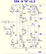
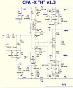
Lower value resistances are for lower voltage supply rails. You could squeeze on a 2W resistor in those locations and stand it off the board. I believe the 5K6 value was optimal for 60-70V rails, you could likely go up to 6K8 the reduce dissipation and still provide enough current to operate the shunt regulators. Whatever you do don't reduce the value! The current will increase and dissipation goes up with the square of current.
Thanks Terry,
It is hard to comprehend that all the different implementations of input sections and output sections would all be compatible as originally designed without modifications to make each combination stable over the entire bandwidth of these designs. I look later and see if in fact the oscillation is not present in the original configuration.
It is hard to comprehend that all the different implementations of input sections and output sections would all be compatible as originally designed without modifications to make each combination stable over the entire bandwidth of these designs. I look later and see if in fact the oscillation is not present in the original configuration.
- Home
- Amplifiers
- Solid State
- SlewMaster Builds