This has got to be the best comment on these threads I have ever heard so far. Shows a great detail of knowledge of amplifiers and the process in which to fault find them properly. Thanks Bigun in spending your time to share this wealth of knowledge. Now I am off to print the schematics and follow your process to learn something as well.Hi Terry,
Let's look at those voltages you posted and see if we can narrow it down a bit more.
The voltage across R10 is too high - clue 1. It says we have too much current flowing through it 8V/1k = 8mA - where is it going ? Well not through the base of Q8 (this wouldn't be normal for Q8 anyhow) since it would then appear through R11. The voltage across R11 allows me to calculate that we have only 0.2mA there. So it's going through Q7 (as it should) and then provides current for the LTP that sits on the negative side of the circuit.
The current should then flow through R7 & R8 into Q3 & Q4. The voltage drop across R7 shows 14mV, so current = voltage / resistance = 14/22mA = 0.6mA which is about right. The voltage drop across R8 is 154mV, so the current is 7mA. Ah, now we know where all that current through R10 is going, it's going into the emitter of Q3. Q3 and Q4 measure the input signal (base of Q4) and the output signal (base Q3) and compare them - this is your feedback error amplifier. It's an LTP - Long Tail Pair. Invented by the Brit's during the war for radar it works very well. This design is a bit complex because it has two LTPs.
This excessive current flow into the LTP will unbalance it and produce a dc-offset at the output. The other LTP, the upper one will try to fight this so it will reduce the amount of dc-offset but can't completely null it out. This is what you are seeing.
But why is the current source flowing too much current in the first place. The finger points at the current source. This current source could be thought of as a simple feedback arrangement. Q8 monitors the current flow through R10 and throttles it back by modifying the voltage at Q7's base. So if Q8 isn't working properly we have a problem. Also, Q8 has D5 in it's emitter circuit which modifies how Q8 measures the current flow through R10. This is to allow the current to be further throttled back if the temperature of D5 increases. So if D5 isn't working properly we also have a problem. I'd look carefully at these parts, maybe replace D5 (a pitty as I notice you did a really neat job of wiring it up). It seems to me there is far too much voltage across D5 and I think this is where the issue lies. Try replacing D5, check it's not backwards or something, or that your version of the BD140 doesn't have a different pinout for some reason.
By the way, since there is a feedback going on in the current source it is possible for the current source to oscillate and in my design I included a small 1nF capacitor between the base and collector of Q8 to slow it down.
Regards
Simon
I bought them for a seller named alweit on ebay.
Ahh, yes. He sold me some jfets once; good seller.
Member
Joined 2009
Paid Member
Thanks Bigun in spending your time to share
It's great to see I was of help. I also like to learn what I can from the folk on this forum, it makes the hobby fun for me.
Still4, you are no further forward than when you started 9years ago.
You have confused your self this time around by rushing to build 3 or 4 amplifiers at the same time. That rushing into multiple builds has incorporated avoidable mistakes.
Slow down. Concentrate on one build and LEARN what is happening.
It is no excuse to say it is "Greek" !
With all due respect, I am much further along than I was 9 years ago.
I was diagnosed with cancer last year. I will decide how slowly or quickly I choose to build amps. I learn something new with each build. I will not be taking any electronics courses so it may take me a little longer to learn it than those of you who did. If my ignorance bothers you, please ignore my posts.
Regards
The only important things in here is first get better and second have fun with what you're doing, after all it is a hobby.
All the best!
Do
Thanks guys. Yes, went through the treatments. So far NED but left with neuropathy and no saliva. Big wake up call. The days we have are a gift and numbered. I plan to make the best of them. I do this for fun. I am learning as I go. It has been great meeting all you fine folks too. That is the best part of this hobby.
Blessings, Terry
Blessings, Terry
Andrew, you are no further along in that time, in learning that everyone has different goals and works in different ways in this hobby. You must take this on board and stop lecturing on this forum. If you don't wish to help, please don't post, rather than telling people off.
 come on guys, DIY is supposed to be fun and that fun is diminished when one imposes on another, let this serve as a warning,,,,,
It's great to see I was of help. I also like to learn what I can from the folk on this forum, it makes the hobby fun for me.
I second niss_man's comments!
Thanks guys. Yes, went through the treatments. So far NED but left with neuropathy and no saliva. Big wake up call. The days we have are a gift and numbered. I plan to make the best of them. I do this for fun. I am learning as I go. It has been great meeting all you fine folks too. That is the best part of this hobby.
Blessings, Terry
I have to say that I enjoy watching your work Terry. I know Andrew wants good to all of us. His advices helped many members here. Bu his style is distinctive little bit.
Hi Guys,
Didn't mean to cast a dim light. Thanks for all the well wishes. I have 4 amps right now that need cases. I need to get to the metal supply house and get some more materials. I hope to get these finished up before I start another but I'm not promising anything.
I'm really hoping to get this one done so I can listen to it properly. I listened to the single channel for a couple hours yesterday and it just seemed to sound better and better as it burned in.
Blessings, Terry
Member
Joined 2009
Paid Member
I hope to get these finished up before I start another but I'm not promising anything.
I suffer from that problem too !
Have you started to look at playing with valves (vacuum tubes) yet ?
I suffer from that problem too !
Have you started to look at playing with valves (vacuum tubes) yet ?
My son keeps after me to build him a tube guitar amp.
Thanks again for all the well wishes.
Blessings, Terry
OK, so I have a blown output. An IRFP9240 to be exact. Rather than order another matched quad, I just ordered some IRFP9240 devices which means I will need to match them myself. My question is will using this circuit for the P-channel device work well enough to match them for this amp? I think Nelson suggests a 2k2 for the resistor.
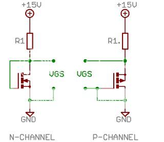
How close in voltage do they need to be to be considered a good match?
Thanks, Terry
How close in voltage do they need to be to be considered a good match?
Thanks, Terry
I received the replacement parts this morning. I have been listening to it for a couple hours now. This is a very good sounding amp. It is slightly darker sounding than the VSSA but not in a bad way. I have been A/B'ing them for a while and it is very subtle but there is just a slight difference. The GB150 is lovely on female voices. I am looking forward to listening to it for a few days.
One thing I did want to ask is the bias setting. I know I had something to work from but I can't find it. I checked the side I had working and it was set at 240mA per rail so I set this side at that too but I don't know it that is right. The outputs are running at about 56C mounted to my test heatsink. I know Nelson uses these output in his Class A amps so I would guess that is OK but I would like to have the amp operating where Greg intended so if any of you know the proper way to set the bias I would appreciate hearing from you.
Blessings, Terry

- Home
- Amplifiers
- Solid State
- SKA GB150D now public domain...