Later in the day
Hi Terry,
Later on in the day the urge to fix that amp will kick in. Order a new set of mosfets and an antistatic strap and work on wooden or bare floor no carpet") .
.
kind regards,
Harrison.
Hi Terry,
Later on in the day the urge to fix that amp will kick in. Order a new set of mosfets and an antistatic strap and work on wooden or bare floor no carpet
.kind regards,
Harrison.
I'm not too familiar with MOSFET amps. I've only built one and that was my first diy amp, a P101<gate is protected>. It is just OK sounding compared to some of the other amps I've built.
Blessings, Terry
Bias pot full clockwise - full bias
Bias pot anti-clockwise - zero bias.
It's the oposite of Greg's boards.
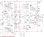
Check the zener mod - is it right implemented? You also can use the RCR mod (less noise because no zener) - R11, R13=100k, R30,R31=330k, C12,C13=100nF.
Thanks, Paulo that was the main issue. I had it backwards. On every amp I have built, higher resistance on the bias pot meant lower bias. This one is opposite and I was too stubborn to try the other end. Now I can bring it up on full rails but I have another problem. I have about 8.4V drop on R10 and 1.27v on R12. -.580V offset on the output. Both boards are the same. I see 14.8V across the two 15v zeners. Any suggestions as to were to look now would be greatly appreciated.
I have the bias set very low right now for safety sake. 19ma per rail.
Thanks, Terry
Member
Joined 2009
Paid Member
The F5 is the same. set bias resistor to zero. start up. prove all wiring and devices are correctly connected.Thanks, Paulo that was the main issue. I had it backwards. On every amp I have built, higher resistance on the bias pot meant lower bias. This one is opposite and I was too stubborn to try the other end. Now I can bring it up on full rails but I have another problem. I have about 8.4V drop on R10 and 1.27v on R12. -.580V offset on the output. Both boards are the same. I see 14.8V across the two 15v zeners. Any suggestions as to were to look now would be greatly appreciated.
I have the bias set very low right now for safety sake. 19ma per rail.
Thanks, Terry
Then adjust the bias pots up to set up output device currents.
Member
Joined 2009
Paid Member
Member
Joined 2009
Paid Member
Quick question like that... Are we limited to using IRFP240/9240 or 2SK1530/J201, 2SK1058/J162 (with reversed source and drain) are also a possibility or not recommended?
Thanks
Do
The circuit requires FETs with a Vgs of around 4V so lateral FETs with low Vgs are a problem.
I believe Greg sells the GB100 with lateral FETs and uses a different circuit - I could be wrong.
Maybe the low bias is creating the unballance
that resulted in the offset
FEW usually need huge current.....give it a try....increase it to 200mA and your offset may be fixed.
I had that trouble once.....with FET.....yes....i had
Your output may not be conducting the way it should.
regards,
Carlos
that resulted in the offset
FEW usually need huge current.....give it a try....increase it to 200mA and your offset may be fixed.
I had that trouble once.....with FET.....yes....i had
Your output may not be conducting the way it should.
regards,
Carlos
Hi Do,Quick question like that... Are we limited to using IRFP240/9240 or 2SK1530/J201, 2SK1058/J162 (with reversed source and drain) are also a possibility or not recommended?
Greg was asked that same question at his forum and he answered that laterals will not work in this amp. So, we're limited to IRFPs.
Hi Guys,
I have checked the connections. I replaced D5 three times thinking I might have a bad part. At first I used some BD140's that I bought off ebay. They have an hFE of 250. I ordered parts from Mouser. They have an hFE of 140. The BD139 in D6 has an hFE of 90.
I tried setting the bias and it is extremely touchy. I will jump from 70ma to 500ma in a very slight turn of the pot. With very careful adjustment it is possible to get it to 200ma but the offset is unaffected. With the bias set to 200ma the drop from drain to source is equal on all 4 MOSFETs. Only the gate is different. I still have 8.5V drop on R10 and 1.2v drop on R12.
Thanks, Terry
Member
Joined 2009
Paid Member
Terry, unstable bias is a classic indication of oscillations. This is the problem I had with my TGM7. It took some careful work to sort it out. Can you put an oscilloscope on it ?
In my case the bias was smoothly adjustable up to about the same level as your was, then it went cray. This is why I'm very suspicious you have the same problem.
In my case the bias was smoothly adjustable up to about the same level as your was, then it went cray. This is why I'm very suspicious you have the same problem.
The circuit requires FETs with a Vgs of around 4V so lateral FETs with low Vgs are a problem.
I believe Greg sells the GB100 with lateral FETs and uses a different circuit - I could be wrong.
ok thanks!
The 2SK1530 is a semi-lateral but VGS theshold is max 2.8V... So IRFP here we go!
Thanks
Do
Member
Joined 2009
Paid Member
Just so you know why - the way I see it - the voltage at the gate of the FET is roughly the voltage at the collector of the LTP, less 0.7V drop across the driver device. So lowering Vgs by choosing a different FET means lowering the voltage drop across the collector load of the LTP. To do this you either reduce the LTP current (and it's already at a rather low level of only 0.5mA) or you reduce the value of the resistors. If you reduce the value of the resistors you reduce the gain of the LTP and since you can't increase the LTP current you can't recover this through increased transconductance of the LTP devices. So there is an inherent tradeoff between LTP gain and Vgs. Greg has fine tuned this circuit in many places.
Terry, unstable bias is a classic indication of oscillations. This is the problem I had with my TGM7. It took some careful work to sort it out. Can you put an oscilloscope on it ?
In my case the bias was smoothly adjustable up to about the same level as your was, then it went cray. This is why I'm very suspicious you have the same problem.
It might be oscillating but I'm not sure that means anything at this point. I have a big difference in voltage between R10 and R12. I can't see anything behaving properly until I can get that sorted out.
I just checked and the vbe on all of the small transistors is .6v.
thanks
- Home
- Amplifiers
- Solid State
- SKA GB150D now public domain...