Cool, and congratulations!
Very impressive sensitivity for one box @ 2PI and 2,83 V, actually it is the best I have aver seen from a single box of moderate size, my hat is off.
My own TH's messure 500x550x680mm WxHxD and they aim for roughly the same response and are loaded with B&C's 15TBX100, what are the external dims on these and what driver are you using ?
again, really good work, and thanks for sharing / martinsson
Reverse engineering artistic cabinets.
JB and other "Artists", to reverse engineer your on the fly or tweaked boxes:
Do the foam trick but in reverse. HD or Lowes pick up 3/8 insulating foam in a 4x8 sheet foiled both sides. Draw the cab profile out with a marker and cut out the pieces.
Then simply lay them out in a straight line and measure them. That should give you really close numbers to throw into hornresp. Perhaps DJK or someone could suggest the best cut points/angles in the corners.
I lay out my boxes that way to start with so I can see what will fit without redrawing it over and over.
Hornresp to straight foam layout, test fit/cut foam to fit profile, tweak reflectors etc, build throwaway with screws and nashua aluminum duct repair tape, tweak away, finalize or actually glue together prototype. If I'm going to build a bunch I might leave the prototype with one side (armacell) openable as a reference.
I have done 100w tests with cabinets built this way along with weatherstrip foam or armacell 1/8 tape. Works best on 3/4" plywood cabs. I often tape up the outside as well.
You can also stick the cut pieces into the box to figure out where things like S2 really wound up in the build. You'll probably find it drifted due to the angles...")
Use the heavier Nashua tape as it's easier to remove and it can be used to cover both sides of a screw hole when tweaking. The thinner stuff is a pain to pull off but works almost as well.
I've tested a few boxes at full blast screwed and taped...no glue. Might be tricky with 1/2 inch wood.
JB and other "Artists", to reverse engineer your on the fly or tweaked boxes:
Do the foam trick but in reverse. HD or Lowes pick up 3/8 insulating foam in a 4x8 sheet foiled both sides. Draw the cab profile out with a marker and cut out the pieces.
Then simply lay them out in a straight line and measure them. That should give you really close numbers to throw into hornresp. Perhaps DJK or someone could suggest the best cut points/angles in the corners.
I lay out my boxes that way to start with so I can see what will fit without redrawing it over and over.
Hornresp to straight foam layout, test fit/cut foam to fit profile, tweak reflectors etc, build throwaway with screws and nashua aluminum duct repair tape, tweak away, finalize or actually glue together prototype. If I'm going to build a bunch I might leave the prototype with one side (armacell) openable as a reference.
I have done 100w tests with cabinets built this way along with weatherstrip foam or armacell 1/8 tape. Works best on 3/4" plywood cabs. I often tape up the outside as well.
You can also stick the cut pieces into the box to figure out where things like S2 really wound up in the build. You'll probably find it drifted due to the angles...
Use the heavier Nashua tape as it's easier to remove and it can be used to cover both sides of a screw hole when tweaking. The thinner stuff is a pain to pull off but works almost as well.
I've tested a few boxes at full blast screwed and taped...no glue. Might be tricky with 1/2 inch wood.
Last edited:
Drawing for simulation in Post #57
Hi jbell,
This is the sketch derived from your dimensions from which I build the simulation in Post #57. As you can see it is not a finished drawing, and some of the dimension just don't quite meet (in the upper left hand corner they are quite a bit of, but that depends on where you start.)
Anyhow, for what it's worth:
Regards,
Attachments
Mike:
Cut sheet is in post #39, sorry to hear about your ribs. BTW, for your next cabinet, put it on an iron diet.... I only use just enough screws to hold things together till the glue dries, usually 2-4 per panel. Then I remove them and fill holes with PL wood filler.
It was raining ALL DAY today, but I finally braved the rain with a tarp, and went outside for a couple minutes testing @ 28v.
replace all those beautiful 105's with 103's.... (sigh) which is in line with what hornresp says I should be getting. Still 123db@28v1M is nothing to sneeze at.
Cabinet felt relatively solid -- much to my surprise. However with a loss of 2db from 2.83v to 28v, tells me something is vibrating and losses are happening. It's possible that I didn't measure well in the rain... and 105 is for real, but I have much more faith in a 103db number....
Jim:
LOL, I did go a little crazy with the cabinet screws. I use bondo after I remove the screws to fill the holes. I have never seen the PL wood filler. Gonna have to check it out. Hate to mention that I used my air stapler on that cab also. Do you think it was a little over kill? If one screw will hold, 10 will hold better. lol I will cut back the iron.
Mike
Jbell, how high can this new design go? do you have plots for 2 / 4 of them.. just out of curiosity have you simmed any other drivers in this? would try my self but Im on a mac so can't run hornsresp
sorry for the all the questions.
I think olivers hornresp is pretty close -- however I always measure lower than what I think I'm building. I read some place on designing FLH, that you need to take into consideration the 'horn bubble' in front of the mouth. Wonder if there is something to that, and that's why my TH's always measure a little lower than I think. For that reason, I've come to design just short of 40hz in hornresp, so that what I build is closer to what I really want.
In terms of how high? I've personally measured/listened up through 200hz in 1hz increments. Other than the 170hz dip (that hornresp predicts, but predicts a much wider in frequency dip) It's smooth up through 200. I'm guessing about 250 is as far as it could be pushed before something starts sounding iffy...
Also, word to the wise... trying to measure over soggy ground over grass in the rain is NOT 2pi space... My driveway measurements at 28v look much closer to my original 2.83v... so I'm not nearly as concerned about panel flex as I was.
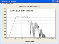
I attached a 2.83v 1 and 4 cabinet hornresp response. I think it's pretty close to the numbers I measured. You can see how hornresp predicts 4 cabinets should get you flat to 40. I actually think 2 cabinets will get you there.
It only costs you a sheet of ply and tube of glue to find out if this cabinet is a good one or not, have fun.
Attachments
You don't have to worry about the "horn bubble" as HR does this end correction for you.I read some place on designing FLH, that you need to take into consideration the 'horn bubble' in front of the mouth. Wonder if there is something to that, and that's why my TH's always measure a little lower than I think.
Last edited:
Jim:
Where is the best placement for these handles on this new design? Dayton PH114 Plastic Pocket Handle 4-Sided | Parts-Express.com Also what are you thinking for a grill?
I was thinking of building some type of frame and using pet screen.
As soon as I get healed up a bit, I will crank one of these out. I got the poster board today, so I can make a template of the layout.
Here is a pic of the template that I finished tonight. Hope I will be healed up enough to start on these sometime next week.
An externally hosted image should be here but it was not working when we last tested it.
Post #63,64,70
Hi jbell,
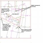
I took your notes and "refreshed" the drawing from Post #63. The Hornresp simulation does not change sufficiently to warrant spending any more time on it. I added a few more dimensions to this drawing, and between your drawing in Post #39 and this there should be enough data for anyone who wants to build one. The builder has to be a little careful with the dimensions after cutting v. the drawing dimensions (saw cuts being about 1/8"), but small differences should not make much of a difference. You squeezed a lot of box out of one sheet of plywood. Well done.
Regards,
Hi jbell,
I took your notes and "refreshed" the drawing from Post #63. The Hornresp simulation does not change sufficiently to warrant spending any more time on it. I added a few more dimensions to this drawing, and between your drawing in Post #39 and this there should be enough data for anyone who wants to build one. The builder has to be a little careful with the dimensions after cutting v. the drawing dimensions (saw cuts being about 1/8"), but small differences should not make much of a difference. You squeezed a lot of box out of one sheet of plywood. Well done.
Regards,
Attachments
It doesn't add up for me...
![url]](/community/proxy.php?image=http%3A%2F%2F%5BIMG%5D%5Burl%5Dhttp%3A%2F%2Fwww.diyaudio.com%2Fforums%2Fattachments%2Fsubwoofers%2F184239d1281914346-single-sheet-th-challenge-picture-199a.jpg%5B%2Furl%5D&hash=faf985d6a42486d4217980313a05d160) [/IMG]
[/IMG]
When I measure from back to front like in the photo above it doesn't add up. I will try to explain the best I can. Here goes...
I start at the back and come in a 1/2" and then measure 6" across to the 13.5" panel. Then add a 1/2" for the 13.5" panel. So we are at 7" so far and will add 5.25 to get to the 8" panel. Now 12.25" + 1/2"(8" panel thickness) =12.75". 12.75" + 4.75"= 17.5" to the 6" panel. Plus 1/2" (for 6" panel) gets us to 18" . And adding 4.5" with our 18" gets us to 22.50" to the front of the 13" front panel. It should be 24".
Either I need a good long break(very very very possible) or Lucy got some splaining to do!
Last edited:
I think the SI (Systeme International) is based on cgs.Darn inches... why... metric please
The metric system is based on mks. Stick with metres and kilograms not centimetres and grams. And use multipliers in multiples of 10^3 or 10^-3
Hi jbell,
I took your notes and "refreshed" the drawing from Post #63. The Hornresp simulation does not change sufficiently to warrant spending any more time on it. I added a few more dimensions to this drawing, and between your drawing in Post #39 and this there should be enough data for anyone who wants to build one. The builder has to be a little careful with the dimensions after cutting v. the drawing dimensions (saw cuts being about 1/8"), but small differences should not make much of a difference. You squeezed a lot of box out of one sheet of plywood. Well done.
Regards,
THANK YOU oliver:
Yes, this looks very much like what I built, right down to the 8" board having the matching 27 degree cut. (the cut between the baffle and 8" board was the last cut I made)
Yes, careful cuts with a table saw are the only way I know of to get all this cut out. I literally have a pair of 2" triangles and sawdust left over.
The way I cut it out:
1. Cut a 30x48 off of one end of the ply.
2. Set fence at 21" and cut (3) 48x21, leaving a 2.5" strip for braces.
3. set fence at 23 15/16" (24" center blade) and rip one 21x48 and 30x48 into top/bottom/side/side
4. cut out the other parts, leaving the 27degree cut between baffle/8" board for last.
It really cuts out fast, and assembles fast. PL glue takes care of any of the angles that are not exactly 90 degrees.
This is a great effort in balancing the use of materials with results. Thanks to all.
Would I lose "style points" if I chose to make the side panels (or the whole thing) from 3/4" stock?
Would I fall out of the category for using corner blocks (3/4" x-section) throughout?...even if I robbed them from the scrap pile?
Would I lose "style points" if I chose to make the side panels (or the whole thing) from 3/4" stock?
Would I fall out of the category for using corner blocks (3/4" x-section) throughout?...even if I robbed them from the scrap pile?
- Home
- Loudspeakers
- Subwoofers
- Single sheet TH challenge