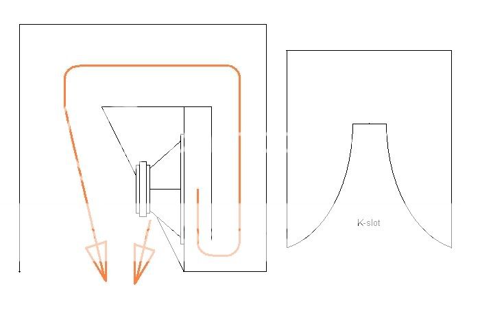
Far as I know, for the last 1/3 of the line K coupled: to continue transforming impedance
in similar manner to a horn should either be straight or tapered down. Expanding does not
help here... Zobsky built a BLH like that to RCAFan spec, it sounded like a coffin. A big
cardboard scoop helped some, but wasted internal volume could have been better used.
KSlots also require hugely different air volume on exit side to transform impedance.
Can't have a series of them stuffed inside a straight line do anything useful. Don't
work good to face the slot toward a corner. Counterintuitive to horn thinking...
Simulated K slot loading? Unless you got computational fluid dynamics skills, I doubt it.
You gonna have to break it down to smaller chunks or something...
The slot you drew also looks way too short, may not behave any different than a port.
1/3 to 1/2 the length of the line needs to be slotted. Most of that slot can be narrow,
so narrow it looks useless, but existence of a logarithmic leak is required for it to work.
Get you Klipsh tiepins ready for the flipping...
Last edited:
Sorry, but I'd like to go back to the SS15
Hi Xoc1,
Nice work in Post #737, what is your Hornresp input?
Hi Djim,
In Post #723 I mentioned Solid Edge 2D, by Siemens PLM software. It's free, and will take care of most 2D drawing needs. Just download, and try.
Regards,
Hi Xoc1,
Nice work in Post #737, what is your Hornresp input?
Hi Djim,
In Post #723 I mentioned Solid Edge 2D, by Siemens PLM software. It's free, and will take care of most 2D drawing needs. Just download, and try.
Regards,
Last edited:
I plan to build a tapped horn based on the ss15, I have 2- 15" Eminence pa speakers, more mid I think with the 80oz magnets and 14bl but for hi-fi, planning stretching the box to 36" high and 18" internal width-hornresp predicts a small peak at 55hz and down from there. Have been following this thread for a while. I have these pa speakers allready.
Hi Xoc1,
Nice work in Post #737, what is your Hornresp input?
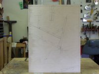
I added some dimensions to sheet 2 to approximate the hornresp input.
Width is 533 so multiply the height dims by 5.33 for the areas.
The horn length to S3 is entirely a guess as the actual shape is curved.
There are 2 dimensions at S4 & S5 that I overlapped, S4 being 344mm (1833.52 cm sq) which includes an allowance for the driver of 18mm and s5 is 410mm (2185.3 cm sq)
Does anyone have ideas how these might be simulated?
DJK,
Hornresp is based on a circular horn cross section, various shapes are not possible to model. Changing the circular cross section to high aspect ratio rectangular real world construction opens up many opportunities for the real cabinet response to vary quite a bit from a model.
I don’t know if other programs allow for different shape cross sections and mouths, but even if they did, they would probably exhibit higher “Q” results than the actual cabinet does, as the simulations I have seen presently do.
For a simulation program to be accurate, it has to follow real world results, not the other way around.
Hornresp predicting a lower LF corner for multiple TH is another example of a program not following real world results.
As I knew that it would not be possible to simulate different mouth shapes, once I was happy with the simulated frequency response and output level for the basic horn plan of what became the Keystone, I experimented first with basic rectangular exit areas, full width of the horn, then with various shapes.
Various corner ramps were added and discarded during the tests after they proved to have inconsequential effects within an octave of the upper pass band with this particular fold pattern.
The basic rectangular exits are not on the "A-V" test descriptive pictures, since they could easily be recorded as simple areas from 200 square inches to 1087 square inches, which was no front panel at all.
As well as the tests saved, many interim tests were performed, the tests listed are probably only 25% of the actual tests done.
Tests “I” and “U” were fairly close to the Karlson shape. At the low frequency pass band of a sub, the curved aperture of the Karlson shape would test little different than straight lines approximating the shape, after those shapes proved less effective than the Keystone shape, having less upper and lower response with more peaks (pretty much what one would expect from the Karlson shape L.O.L) I found no reason to try any further homage to Karlson.
Real tests made outdoors, away from buildings, with decent test gear trump simulations. Note that I did not stop at test “S”, pretty much the Keystone mouth exit as built, many other shapes and sizes tested before and after were tried.
Back to the SS15, by closing the front panel, and putting the exit on the panel opposite from the speaker, the same tests could be conducted on it.
I think it possible the SS15 in such a configuration, using a Keystone exit, might load a bit lower and still retain, or even better, the upper response.
Attachments

")

I am starting with 8.how many are you bilding?
You will!like to see the end result
Maybe I should start a new thread?
I am starting with 8.
You will!
Maybe I should start a new thread?
Absolutely you should... You made this project your own. While it has a resemblance to the SS15 design, it's yours... I applaud your willingness to learn what and why. And then with that knowledge, going forward and doing.
Knowing what and why is always better than just building someone else's plan and hoping.
Enjoy the sawdust in the air... it's a beautiful thing.
- Home
- Loudspeakers
- Subwoofers
- Single sheet TH challenge