bocka,
and what to do when there is 2nd harmonic of some -115dB, 3rd of some -120dB, IMD of similar order, no higher harmonics, class A, and you find that it is not THD and IMD what makes a difference, but filtration, CD signal treatment, cable termination etc? That most of the standard approaches to solve sound problems are simply wrong?")
and what to do when there is 2nd harmonic of some -115dB, 3rd of some -120dB, IMD of similar order, no higher harmonics, class A, and you find that it is not THD and IMD what makes a difference, but filtration, CD signal treatment, cable termination etc? That most of the standard approaches to solve sound problems are simply wrong?
Well stated, Bocka. Most of our distortion is in the output, followed by the high voltage driver that has to develop the complete voltage swing for the amp. The input stage used to be a big problem when we used maximum Gm input stages. This was because the input stage would work harder and harder with increasing frequency, ultimately causing slew rate limiting, and even earlier, TIM (or SID). Walt Jung and Matti Otala have published reams of info in this, beginning in the 70's.
Today, we all degenerate our bipolar input stages, increase our gain-bandwidth of our amp, or both. Fets usually don't have to be degenerated in order to get a very high slew rate, because they are always lower Gm than non-degenerated bipolars, and they are more linear as well.
Today, we all degenerate our bipolar input stages, increase our gain-bandwidth of our amp, or both. Fets usually don't have to be degenerated in order to get a very high slew rate, because they are always lower Gm than non-degenerated bipolars, and they are more linear as well.
boska wrote:
Obviously a VAS stage has a high output and typical bipolar stage a very non-linear input impedance witch is the main mechanism of crossover distortion in a bipolar output stage.
Sorry this is true _only_ when the _open_ loop VAS is taken into account. When you speak about Self/blameless design you should have in mind that because of the local loop through frequency compensation capacitor the vas output resistance will _lower_ with frequency. Definitely it wouldn’t be the “main mechanism”.
Hi,
What keeps on surprising me is how tube and transistor problems are similar....
Not knowing all that much about semis, you can still read JCs post as if it were tubes he talked about .
It's perfectly understandable to both parties...absolutely brilliant.
Than there's Matti Otala's work regarding TIM and other distortion artefacts that no oscope shows up...
Suddenly I feel at home...great!!!
Cheers,
Frank,
Please......you talk like you might build a solid state amp soon.
Here is some fun reading for you....to get in the mood.
http://users.arczip.com/rmcgarra1/xstrhist.html
Regards,
Jam
Please......you talk like you might build a solid state amp soon.
Here is some fun reading for you....to get in the mood.
http://users.arczip.com/rmcgarra1/xstrhist.html
Regards,
Jam
Hey Jam,
I do? I wouldn't count on it if I were you...
Let's just say that I'm at awe with JC's knowledge and I really find myself in his thinking and your sense of humour at the same time...
There's still way too much for me in the tube department to be learned, a field that I'm really passionate about, before I even think of looking into semis.
The more I learn, the more I realise I don't know nothing at all...don't even know if that's a proper English expression...
Be my guest and educate this hopeless Rita...
Please......you talk like you might build a solid state amp soon.
I do? I wouldn't count on it if I were you...
Let's just say that I'm at awe with JC's knowledge and I really find myself in his thinking and your sense of humour at the same time...
There's still way too much for me in the tube department to be learned, a field that I'm really passionate about, before I even think of looking into semis.
The more I learn, the more I realise I don't know nothing at all...don't even know if that's a proper English expression...
Be my guest and educate this hopeless Rita...
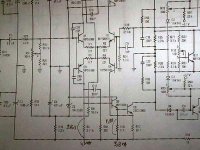
I have another "dumb" question. Look at sch1.jpg. I got this design from Randy G Slone book, about the "Optimum Power Amp". The schematic is very nice to see, complementary differential with current mirror, the VAS is cascoded with 2 transistors.
But when I make experiment of it, this design just doesn't work. Up until now I cannot figure what is the voltage in the base of Q11 and Q12 (first VAS transistor). I need it to determine the VAS's standing current. But the base of Q11 and Q12 is located between collector of differential and collector of current mirror. How can I calculate the voltage between 2 collectors?
When I just change the current mirror with ordinary resistor, this amp work. But how come the author have measurement figures, if the amp doesn't work?
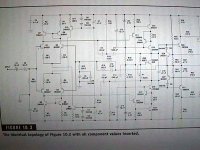
Question no2. comes in sch2.jpg. This is the power amp from motorola. Why is the collector pin of Q2 and Q4 doesn't tied up to +/-VCC with it's own resistor? Q1 and Q3 tied up to +/-VCC via 2.21k resistor. In ordinary design, the Q2 and Q4 will go straight to +/-VCC or via another 2.21k. In that design, both collectors are tied to the VAS's resistor, the 22,1ohm resistor. What is the point of this design, and what is the advantages and disadvantages?
But when I make experiment of it, this design just doesn't work. Up until now I cannot figure what is the voltage in the base of Q11 and Q12 (first VAS transistor). I need it to determine the VAS's standing current. But the base of Q11 and Q12 is located between collector of differential and collector of current mirror. How can I calculate the voltage between 2 collectors?
When I just change the current mirror with ordinary resistor, this amp work. But how come the author have measurement figures, if the amp doesn't work?
Question no2. comes in sch2.jpg. This is the power amp from motorola. Why is the collector pin of Q2 and Q4 doesn't tied up to +/-VCC with it's own resistor? Q1 and Q3 tied up to +/-VCC via 2.21k resistor. In ordinary design, the Q2 and Q4 will go straight to +/-VCC or via another 2.21k. In that design, both collectors are tied to the VAS's resistor, the 22,1ohm resistor. What is the point of this design, and what is the advantages and disadvantages?
Attachments
A question of voltages...
Hi Lumanauw!
The voltage in the base of of Q11 is 1,2volts (two diode drops) under the rail positive voltage!
Ex. If the rail is + 40 volts the voltage at the base of Q11 will be 38,8 volts!
In Q12 will be the some but with negatif voltage!(two diod drops from the minus rail)
This is for some inside feedback loop...it can increase stability and linearity..
Advantages..as expressed formely more stability and linearity in open loop...
Disadvantages...less open loop gain for more overall feedback for less overall distortion...
See one example of this technic in a design of our forum friend Jonh Curl:
http://marklev.com/marklev/JC3/jc3schematics.jpg
Regards!
Hi Lumanauw!
Up until now I cannot figure what is the voltage in the base of Q11 and Q12 (first VAS transistor).
The voltage in the base of of Q11 is 1,2volts (two diode drops) under the rail positive voltage!
Ex. If the rail is + 40 volts the voltage at the base of Q11 will be 38,8 volts!
In Q12 will be the some but with negatif voltage!(two diod drops from the minus rail)
Question no2. comes in sch2.jpg. This is the power amp from motorola. Why is the collector pin of Q2 and Q4 doesn't tied up to +/-VCC with it's own resistor? Q1 and Q3 tied up to +/-VCC via 2.21k resistor. In ordinary design, the Q2 and Q4 will go straight to +/-VCC or via another 2.21k. In that design, both collectors are tied to the VAS's resistor, the 22,1ohm resistor. What is the point of this design, and what is the advantages and disadvantages?
This is for some inside feedback loop...it can increase stability and linearity..
Advantages..as expressed formely more stability and linearity in open loop...
Disadvantages...less open loop gain for more overall feedback for less overall distortion...
See one example of this technic in a design of our forum friend Jonh Curl:
http://marklev.com/marklev/JC3/jc3schematics.jpg
Regards!
Sorry this is true _only_ when the _open_ loop VAS is taken into account. When you speak about Self/blameless design you should have in mind that because of the local loop through frequency compensation capacitor the vas output resistance will _lower_ with frequency. Definitely it wouldn’t be the "main mechanism".
dimitri,
yes, you're completely right about the Doug Self stage with compensation capacitor as it gives local feedback to the VAS stage. I'd be a little more precise about this. If we'd use an uncompensated or open loop VAS stage we can see, that a typical bipolar output stage will load the VAS stage witch results in heavy high order distortion of the output stage.
I think in this point of view tubes and bipolar are quite different. Tubes in class AB will have lower distortion levels and lower high order distortion without any applied feedback.
To my opinon and experiance an amp with low inherent (feedbackless or open loop) distortion sounds better with applied feedback. One possibility to archieve this is to use an output tripplet or a MOSFET output stage.
> I have another "dumb" question. ...design from Randy G Slone book, about the "Optimum Power Amp". ...when I make experiment of it, this design just doesn't work. Up until now I cannot figure what is the voltage in the base of Q11 and Q12 (first VAS transistor).
I think this was discussed before, and the consensus is that it will not work as shown. As your "dumb" (not dumb!) analysis shows, the current in the second stage is not clearly defined. As Tube Dude says, to "work" it has to be something like 2Vbe. But circuits do what you make them do, not what you think they will do. In this case there is nothing that "makes" the second stage current any particular value.
This goes back to Nelson's comment about how nice it is to have one side setting currents throughout the amp: "the bias stability that such arrangements provide." You can do both sides, but there are ways to go wrong that you may not notice until you smoke a boardful of transistors. Old-hands like Pass and Curl are either smart enough or smoke-experienced enough to see these on paper, but I can still do equally dumb things despite years of smoking parts.
> how come the author have measurement figures, if the amp doesn't work?
I suspect the wrong diagram got printed, or the publisher's artist re-drew the author's sketch wrong.
Actually: if the input quad is perfectly matched, the second stage can only draw a "very small" base current. With luck, the stage may wind up somewhere between cut-off and smoking, and actually amplify. It is not impossible that it would work. But it is hypersensitive to part parameters and generally won't work except by luck.
> power amp from motorola. Why is the collector pin of Q2 and Q4 doesn't tied up to +/-VCC with it's own resistor?
Returning the other side of the diff-amp to the next stage emitter gives some of the benefit of a current mirror without some of the problems. To my eye it is "ugly", but often useful.
Nelson Pass said:I'm a bit surprised that no one has mentioned one of the
advantages of single-pair inputs biased by a constant
current source and driving an SE 2nd stage which is loaded
with a constant current source - namely the bias stability that
such arrangements provide. It is easy to make a stable CCS,
and this stabilizes the operation of the gain devices.
Isn't this an aleph with a ccs?
> What keeps on surprising me is how tube and transistor problems are similar....
They are identical. Just a different balance of problems.
BJT has a "junction" that current won't cross without a certain energy, and the amount of current can be calculated.
FETs have a bulk resistance that can be "squeezed" by an external field, but the edge of the squeezed area is a junction.
Thermionic vacuum tubes have a little of both. The cathode surface is a junction, just not a solid-state junction because one side isn't solid. But when you get down on the atomic level and look how electrons come off the cathode, you have to use the exact same physics as transistor theory. However, most of the energy applied to this junction is "heater", not Signal. Then the electrons pass through a "bulk" which is squeezed and stiffled by electric field.
Philosophically, "all devices are the same".
Yes, practical devices differ enough to hide the underlying unity of all electronics.
Differences:
* atomic-size junction or bulk effect
* parasitics
The practical vacuum tube is far from perfect. Cathodes hang onto electrons very hard. Somehow the cathode matter must be fluid enough to loosen electrons while solid enough to hold a shape. In operation, a monatomic layer of the surface is above melting-point while the rest of the cathode is solid. Very tricky (and poorly understood) doping is needed for great results. Then the bulk of the tube would control poorly if designed to classic "ideal cylindrical triode" geometry, real tubes use gimicky geometry to improve gain in the normal operating range. The theory books talk about 3/2-Law: you won't catch a practical triode amplifier doing any such thing.
The modern (since 1965) BJT is nearly "ideal", in the sense that the theory is clear (and simple) and practical devices follow theory extremely closely. Also the atomic-sized junction with minimal bulk effect gives the absolute best transconductance of any device. (Though it is worth noting that if we had very clean Germanium, Gm would be twice that of Silicon.) A significant drawback is that all BJT devices require a significant and not clearly defined input current.
The FET is a bulk device and all about geometry and clever device design. Within the range that the device is intended for, we can use simple theory for small signals, but the large signal parameters are all empirical. And the bulk geometry means the Gm tends to be lower than a BJT (though oddly this is untrue at super-low currents). The bulk geometry also means that FETs have significant capacitances and thus can draw large input currents in AC amplifiers, and for large FETs sometimes more current than a BJT even inside the audio band.
You can treat tubes and FETs as BJTs that buffer (more or less) their inputs but have big variable resistors hanging on them. A BJT-nut will argue: take the gain without the losses, use BJT with precision fixed resistors. BJTs do have some bulk effects but we can cascode them away. On the other hand, if you keep adding things to fix the big errors, you end up with a growing pile of "small" errors that can get out of hand. There are a lot of many-BJT plans that are more clever than smart. This even infects tube-heads.
It's not just the device. It's not just the geometry. It's not just the detailing. Everything has to play together nice.
If a certain device or geometry is forced upon you (personal preference, price, existing board), you can probably detail it to a very high standard (higher than commonly found in real life).
If you have a clean-sheet, it is hard to screw-up a simple tube amplifier. At a higher standard of precision, a reasonably simple and easily understood BJT design can work extrememly well (and a lot cooler than tubes). When your specs seem to suggest very complicated BJT designs, you may find that an FET design will do the job without as many "small side effects", because they are a nice compromise between the fairly low gain and precision of tubes and the hyper-high and hard-to-control gain of BJT.
But when the "spec" is the musical ear, some imprecision is ignored and other faults are pinpointed. The ear is a flawed but very clever thing. We can stand in a field of chirping crickets and hear the toe-step of the tiger that is about to eat us (if our ancestors did not hear this well, we would not be here). The ear makes 10% distortion and is unflat 40+dB, but can pick-out a tone 20dB below the general noise level. The measurements that are easy are often not that important. We are nearing the point of machines as clever as the ear, but we are not using them in the same clever way as the ear.
PRR said:>
I think this was discussed before, and the consensus is that it will not work as shown. As your "dumb" (not dumb!) analysis shows, the current in the second stage is not clearly defined.
This has been discussed in
http://www.diyaudio.com/forums/showthread.php?postid=195526#post195526.
I wonder whether these current limiters in the VAS cascode stage (small print, but it seems to be Q14 and Q17 with 33Ω resistors) have something to do with the undefined bias point. At least the VAS current will be limited to approximately 20mA. If so, could that mean that Slone knew it was undefined and used this as a way to 'define' it? Not very sophisticated.
Steven
re: Sloan's ckt working or not ...
I've got two questions:
1. Did anyone build a version to see what would happen?
2. Did anyone ask Sloan to see what he had to say (" there is a diagram error" or "it really does work as long as you maintain the global feedback loop" or ... etc.)
mlloyd1
I've got two questions:
1. Did anyone build a version to see what would happen?
2. Did anyone ask Sloan to see what he had to say (" there is a diagram error" or "it really does work as long as you maintain the global feedback loop" or ... etc.)
mlloyd1
lumanauw said:.... this design just doesn't work....
PRR said:But when the "spec" is the musical ear, some imprecision is ignored and other faults are pinpointed. The ear is a flawed but very clever thing. We can stand in a field of chirping crickets and hear the toe-step of the tiger that is about to eat us (if our ancestors did not hear this well, we would not be here).
Or the toe-step of the tiger that's not there at all.
One of the reasons our ear/brain system isn't quite the highly accurate detection system that some tend to portray it is because nature has wired us to OVERdetect. In other words, we're more prone to perceive a toe-step when there is none than to not perceive one when there is.
This unfortunately makes it rather trivially easy to cause people to perceive differences in audio even when there are none.
We are nearing the point of machines as clever as the ear, but we are not using them in the same clever way as the ear.
Like hearing tigers that aren't there?
Anyway, yeah, the ear/brain system is pretty amazing. But I think in the world of audiophilia, it often gets oversold and there's a tendency to ignore its very real limitations.
se
> nature has wired us to OVERdetect. In other words, we're more prone to perceive a toe-step when there is none than to not perceive one when there is.
On one hand, that's a good point. It is certainly safer to flinch at a hundred non-tigers than to not-hear just one actual tiger. If the tigers or wolves or fruit-tree branches don't get you, your fellow man is probably sneaking up behind you with a rock. Through most of mankind's history, life has been dangerous and some of those dangers can be heard coming. OVER-detect!
On the other hand, this one simple thought could tear-away the cherished foundations of both the "I know what I hear" and the "measurements don't lie" schools of hi-fi philosophy.
Yes, actually I have made it. The output is just big voltage plain DC, which is not affected at all with music. First I got confused with it. But when I replace the current mirrors with resistor with calculated value, it works. But the sound is not very good.
Is there anyway to determine voltage between two collectors (like between collector of differential with collector from current mirror?
Is there anyway to determine voltage between two collectors (like between collector of differential with collector from current mirror?
- Status
- This old topic is closed. If you want to reopen this topic, contact a moderator using the "Report Post" button.
- Home
- Amplifiers
- Solid State
- Single or dual differential?