Wavebourn,
Right. Shall we call it deep feedback over (not more than) two devices? All output voltage, product of the gains of two devices is utilized, like in the Darlington pair, for instance.But the tube is an extra stage in the feedback path that has a gain, while a FET output stage has a gain as well! In the original schematics both tube stage and FET stage have a voltage gain, then they are surrounded by a GNFB to bring gain to 1. Isn't it too many stages according to your principles?
Also, you can have multiple cascade gain blocks consisting of two gain stages each within a fb loop, each with it's own compensation for the audio band (and up to Ft), and have a global loop acting as a DC servo.")
Of course cascodes don't count as gain stages. But then with all that, you will be sure to here from the "that's too many damn transistors" crowd.
Of course cascodes don't count as gain stages. But then with all that, you will be sure to here from the "that's too many damn transistors" crowd.
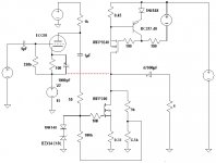
kenpeter said:And this is closer to the version of the schematic I was
searching my drives for earlier... Where both output
MOSFETs are of the same channel. And the top current
source is a fully active helper.
This version only lacked a servo.
Big difference in that my feedback was to the plate.
Hi kenpeter,
interesting schematic. The active current source reminds me of Nelson Pass's designs. Basically it is a Shut Regulated Push Pull circuit and not single ended.
Very interesting the feedback into the plate, I have never seen this before but it should work. However, I would assume that the amount of feedback will be quite limited because the gripthrough (I hope this is the right word, in German the word is "Durchgriff"[influence of plate voltage divided by influence of grid voltage on the plate current]) is only several percent.
Cheers
KLausB
Got to disagree. And I designed it weird that way on purpose.
Misbehavior in circuit most equivalent to single ended parallel.
The active load here is not a normal complimentary push pull.
Its more of an "insult"ramentary single ended push - antipush.
Like when your evil clone reaches out of the mirror and
slaps you in the face (a common problem these days)...
Everything nonlinear about it is bent backward, and the
even harmonics are preserved.
I can point you to threads where the proofs are explained in
greater detail. But both Aleph and AntiTriode are old news.
This current source merely grafted together the best parts
of both (and got rid of a coupling cap typical to Aleph).
I think the overall voltage gain should be around 2*(Mu-1)?
This includes the influence of the plate resistor divider, that
fold back toward B+. To keep the plate from ever dropping
quite so low that G1 conducts excessively and ruin the math.
Or you can think as giving the Triode's plate to the MOSFET
as-if a virtual screen. And 50% UL feedback to that screen.
1/(Mu-1) is the plate feedback figure you are searching for???
Oldeurope has plenty to say in your language on that subject
(the 4th circuit)... And probably can explain it better than I do.
Gripthrough/Dirchgriff?? Either will do. I don't think there is
any well established English word for it.
I went on with some simulation of my circuit. I am still concerned about the high frequency behaviour. I removed the feedback loop and simulated the open loop high frequency response with different source resistors.
0.00 ohm: -3db @ 46 kHz
0.10 ohm: -3db @ 67 kHz
0.33 ohm: -3db @ 108 kHz
Furthermore the triode might be changed against a type with a lower plate resistance. I browsed through the datasheets and found that the KT88 in triode mode has 670 ohm plate resistance. Unfortunately I have no KT88 model tha runs on LTSPICE.
Hi kenpeter,
I disagree. Your circuit is a push pull design. One transistor opens up and simultaneously the partner transistor shuts down. Certainly a shunt regulated design will behave differently compared to a standard PP design, driven by phase splitter stages or a NPN / PNP topology.
Cheers
KlausB
0.00 ohm: -3db @ 46 kHz
0.10 ohm: -3db @ 67 kHz
0.33 ohm: -3db @ 108 kHz
Furthermore the triode might be changed against a type with a lower plate resistance. I browsed through the datasheets and found that the KT88 in triode mode has 670 ohm plate resistance. Unfortunately I have no KT88 model tha runs on LTSPICE.
kenpeter said:Got to disagree. And I designed it weird that way on purpose.
Misbehavior in circuit most equivalent to single ended parallel.
The active load here is not a normal complimentary push pull.
Its more of an "insult"ramentary single ended push - antipush.
Hi kenpeter,
I disagree. Your circuit is a push pull design. One transistor opens up and simultaneously the partner transistor shuts down. Certainly a shunt regulated design will behave differently compared to a standard PP design, driven by phase splitter stages or a NPN / PNP topology.
Cheers
KlausB
Attachments
KlausB said:I browsed through the datasheets and found that the KT88 in triode mode has 670 ohm plate resistance. Unfortunately I have no KT88 model tha runs on LTSPICE.
Try 12L6GT -- a killer driver for hybrids, not discovered yet by audiophiles so is not expensive.
KlausB,
you should not simulate too much, it only gives you bad ideas. A triode is the right device here, ECC88 has low plate resistance. BTW, I would use the other half in the place of the 1k resistor.
you should not simulate too much, it only gives you bad ideas. A triode is the right device here, ECC88 has low plate resistance. BTW, I would use the other half in the place of the 1k resistor.
Try to find a better MOSFET.I am still concerned about the high frequency behaviour.
KlausB said:Hi kenpeter,
I disagree. Your circuit is a push pull design. One transistor opens up and simultaneously the partner transistor shuts down. Certainly a shunt regulated design will behave differently compared to a standard PP design, driven by phase splitter stages or a NPN / PNP topology.
Cheers
KlausB [/B]
I specify identical, and possibly (depending how they are driven)
complimentary behaving transistors. But I do not drive them as
compliments. Other than RDS_On, completely insulting each other.
They are each in tight local feedbacks that define two behaviors.
Each very different from each other, and both different from the
natural MOSFET curve set. Designed to emulate a parallel single
ended stage (as the load sees it) not push pull as it may appear.
When these wonder twins activate, the bottom takes the form
of a Triode's Mu. The top takes the shape of a Transistor's VBE.
Because VBE tracks Mu, but from the other side of the mirror, it
then becomes an Anti-Triode. And then there's that darn purple
monkey, nobody can explain...
Yes, I will probably switch to the BUZ900 instead of the IRFP240.
I never heard about anti-triodes before. I went to your posts at
http://www.diyaudio.com/forums/showthread.php?s=&threadid=140699&perpage=25&pagenumber=1
Are anti-triodes another term for the active current sources?
Cheers
KlausB
I never heard about anti-triodes before. I went to your posts at
http://www.diyaudio.com/forums/showthread.php?s=&threadid=140699&perpage=25&pagenumber=1
Are anti-triodes another term for the active current sources?
Cheers
KlausB
KlausB said:Are anti-triodes another term for the active current sources?
Yes. Anti-Triode / Aleph , basically share the same function.
Words familiar to the other side of the sand/glass curtain.
Many ways to derive an active anti-complimentary current.
Lumba Ogir said:KlausB,
that one would be really nice.
My question is, how many tubes can you use per channel?
Why would he need to use more than one real triode?
His circuit already multiplies virtual copies.
My earlier intent was to show how he could further double
upon this existing effect with an active current source.
------------------------------------------------
The lower half of his White Cathode Follower approximates
an anti-triode'd current source. And cooperates the single
ended aspect of his reference triode to pretend single ended.
If you then anti-compliment again on the top half, you have
a parallel bank of virtual Triodes. Or something pretty close.
Why should anyone prefer to build a current source out of a
triode (voltage amplifier device)? Tetrodes, Pentodes and/or
Sand are the better regulators of a pure current. I suppose
you could get there with a cascode of Triodes, but why???
Your friend who started this thread already specified the
first purple monkey when he carved out his White Cathode
Follower from a device with bigger GM than the reference.
Behaving as-if an Anti-Triode in parallel with a CCS....
Even if he now uses only pure CC Sink for the top end of his
output totem, at least one anti-triode is still present in the
lower half of his WCF.... It is there because the error signal
from his plate tells it to be.
If he were to use the traditional matched Triode for the lower
half of his WCF, would still attempt to recurve itself as-if an
anti-triode, but never quite get there. Because the GM of
the error driven lower triode is no bigger than the original.
You can only carve out clean new virtual curves from bigger
bottles and/or sand.
The result of such a compromise is neither compliment, nor
anti-compliment, nor linear. It works well enough if you want
the blended curve, or only need the low output impedance.
It works well enough for White to be remembered for it.
I'm not saying its bad, only that you are shooting in the
dark for a curve you might imagine is compliment, but not.
If we restrict ourselves to "pure" CCS, then why bother to
specify that is must be a triode?
I somehow feel honored to get so many replies and comments. Thanks a lot guys.
Lumba, though I definitely plan to build a single ended power amp I am still in the phase of gathering and putting ideas together. Hence I have not yet specified a certain number of tubes and I am open to ideas.
Certainly I will have a triode VAS stage, either one EC(C)88 system or in case I go for the 12L6GT or KT88 triode mode option I am thinking about using a EL84 in triode mode as VAS. There are a lot of nice twin triodes out there (I like the 6SN7), but I hate to use only one half of a tube.
Another option I simulated was paralleling 3, 5 or 7 EC(C)88 systems to handle the input capacitance problem. This are no problems in a simulation, where all tubes are identically defined through one model, but I read that in real life paralleling increases non-linearity, which makes sense.
English is not my native language, so please allow one question
purple monkey = good idea or bad idea
Concerning gm of the upper and the lower devices, is transconductance really determinating the circuit behavior? Definitely the mosfet has the higher gm, but it works into a 4 ohm load while the triode has a plate resistor of 1k. In the open loop simulation the triode delivers more gain (10x) than the mosfet (7x).
I see the problem mainly in sourcing 3A or more with tubes. I have to think about the active current source options. Will it improve sound or is it the greed for more wattage??
Cheers
KlausB
Lumba Ogir said:KlausB,
that one would be really nice.
My question is, how many tubes can you use per channel?
Lumba, though I definitely plan to build a single ended power amp I am still in the phase of gathering and putting ideas together. Hence I have not yet specified a certain number of tubes and I am open to ideas.
Certainly I will have a triode VAS stage, either one EC(C)88 system or in case I go for the 12L6GT or KT88 triode mode option I am thinking about using a EL84 in triode mode as VAS. There are a lot of nice twin triodes out there (I like the 6SN7), but I hate to use only one half of a tube.
Another option I simulated was paralleling 3, 5 or 7 EC(C)88 systems to handle the input capacitance problem. This are no problems in a simulation, where all tubes are identically defined through one model, but I read that in real life paralleling increases non-linearity, which makes sense.
kenpeter said:Your friend who started this thread already specified the
first purple monkey when he carved out his White Cathode
Follower from a device with bigger GM than the reference.
Behaving as-if an Anti-Triode in parallel with a CCS....
If he were to use the traditional matched Triode for the lower
half of his WCF, would still attempt to recurve itself as-if an
anti-triode, but never quite get there. Because the GM of
the error driven lower triode is no bigger than the original.
You can only carve out clean new virtual curves from bigger
bottles and/or sand.
English is not my native language, so please allow one question
purple monkey = good idea or bad idea
Concerning gm of the upper and the lower devices, is transconductance really determinating the circuit behavior? Definitely the mosfet has the higher gm, but it works into a 4 ohm load while the triode has a plate resistor of 1k. In the open loop simulation the triode delivers more gain (10x) than the mosfet (7x).
Lumba Ogir said:kenpeter,
current sources made up with a triode are not the very best in terms of dynamic impedance, pentodes are better, but a double triode in that configuration gives indeed excellent sonic results.
The question is what KlausB can use in practice.
I see the problem mainly in sourcing 3A or more with tubes. I have to think about the active current source options. Will it improve sound or is it the greed for more wattage??
Cheers
KlausB
KlausB said:English is not my native language, so please allow one question
purple monkey = good idea or bad idea
Purple monkey is not English, just me being silly. Crazy idea.
In this case, the anti-triode (lower half of your WCF and/or
upper half of my plate follower) were both the crazy ideas.
I happen to think both ideas are crazy good. And I think
both can and should be used together.
Right now, you have exactly one triode cathode follower and
one WCF anti-triode (in single ended push pull). Also parallel
with a constant current that does nothing.
You can expand upon that to any number of virtual triodes
and anti-triodes that bias up to the same quiescent current.
Greatly reducing the output impedance.
All you need do is change your constant current sink to an
active anti-complimentary sink. The rest is pure magic.
KlausB said:Concerning gm of the upper and the lower devices, is transconductance really determinating the circuit behavior? Definitely the mosfet has the higher gm, but it works into a 4 ohm load while the triode has a plate resistor of 1k. In the open loop simulation the triode delivers more gain (10x) than the mosfet (7x).
Then you have 70x error correction gain from plate back to cathode?
As long as the lower device can conduct a clean anti-triode transfer
curve with this much error correction feedback, Gm is sufficient.
I was really thinking of brute bridged anti-triode when I made
that statement... single ended push pull transformer coupling...
The Anti-triode in that case is usually grounded, not driven...
Error correction gain in this case is only unity at best.
I'm not so sure the same strict Gm > Triode rule applies to
circuits like yours, where error correction gain is above unity.
Maybe the traditional WCF with similar triodes is a true Anti-
triode SEPP too? The error correction gains might overrrule
the whole "GM needs to be bigger" problem I was imagining....
Your triode and anti-triode each work an equal 8 ohm share
of the 4 ohm AC load. Rest is constant DC current that does
nothing. I am suggesting you could improve that. And more
virtual copies each working an easier share of the real load.
The triode needs to work a fair share of the load, helped only
by parallel copies or push/pull anti-copies. so that it doesn't
observe anything weird about its share of the impedance.
- Status
- This old topic is closed. If you want to reopen this topic, contact a moderator using the "Report Post" button.
- Home
- Amplifiers
- Solid State
- Single-ended mosfet-tube follower