Hi,
I can see a similarity to the VAS stage of a three stage (Linn topology) power amp.
Could this modified darlington be used as a VAS?
I'm thinking R1=100r, R2=68r, R3=390r, R4=3k6, running off +-50Vdc rails. R3 is way below the resistor gain ratio recommended.
Are the improvements in distortion available when used this way?
Can someone sym this? and optimise the resistor values?
What if R4 was replaced with a current source?
AndrewT said:Hi,
I can see a similarity to the VAS stage of a three stage (Linn topology) power amp.
Could this modified darlington be used as a VAS?
I'm thinking R1=100r, R2=68r, R3=390r, R4=3k6, running off +-50Vdc rails. R3 is way below the resistor gain ratio recommended.
Are the improvements in distortion available when used this way?
Can someone sym this? and optimise the resistor values?
What if R4 was replaced with a current source?
This circuit could be used as a part of extremely linear VAS. As Mikhail has mentioned the out2 point is this circuit is linear independent of the load impedance and could be connected to a low-impedance point, i.e. a common base/gate cascode stage. In the article I've mentioned Mikhail does provide some practical VAS applications of his idea, including a fully symmetrical VAS with no overall feedback and excellent linearity. I suspect you'll need to ask him to post these here if he would agree to it.
x-pro
Hi, X-pro,
The ratio of R1/R2 equals R3/R1 and R4/R2. Also the 2 transistors have to be exactly the same? I see....
The ratio of R1/R2 equals R3/R1 and R4/R2. Also the 2 transistors have to be exactly the same? I see....
Where's Mikhael?In the article I've mentioned Mikhail does provide some practical VAS applications of his idea, including a fully symmetrical VAS with no overall feedback and excellent linearity. I suspect you'll need to ask him to post these here if he would agree to it.
lumanauw said:Hi, X-pro,
1) The ratio of R1/R2 equals R3/R1 and R4/R2. Also the 2 transistors have to be exactly the same? I see....
Where's Mikhael?
Please excuse me but I think I am misunderstanding.
Just to clear up things:
R1= 100 ohm
R2= 330 ohm
R3= 107 ohm
R4= 330 ohm
can we agree on this?
If so, the ratio of R1/R2 does not equal R3/R1 and neither R4/R2.
Or I am wrong?
Kind regards,
beppe
Thanks to x-pro, a good explanations!
The circuit is the simplest possible way to improve one transistor amplifier with the implementation of feed forward correction. Need only 1 transistor and 1 resistor to add.
It works and in certain condition very effective.
As usual one transistor or dairlington stage with common emitter it may by used as VAS or as voltage-to-current converter with the next common base stage (for example).
MOSFET combination also possible.
I do not know how to use feedforward error correction in output stage for complex loading because prediction of current-voltage dependence is not possible except for the resistive active load.
For such a simple circuit a simulator data in good agreement with measured one.
There was two other circuits in paper, in djvu attachment.
(For lumanauw ready to send pdf if will know the mail address")
"The ratio of R1/R2 equals R3/R1 and R4/R2. Also the 2 transistors have to be exactly the same? I see...."
Use any transistors or combination BJT MOS but first transistor have a output impedance which should be add to value of R3 with gain factor or reduced from value R1 by notation on http://www.diyaudio.com/forums/attachment.php?postid=857017&stamp=1141087423
For BJT formula how to calculate resistor is on picture of post #23.
The output impedance firs is in series connected with R1 and for error compensation R1 should be less on that value or R3 increased.
For second transistor no need to take into account impedance it nonlinearity compensated!
The circuit is the simplest possible way to improve one transistor amplifier with the implementation of feed forward correction. Need only 1 transistor and 1 resistor to add.
It works and in certain condition very effective.
As usual one transistor or dairlington stage with common emitter it may by used as VAS or as voltage-to-current converter with the next common base stage (for example).
MOSFET combination also possible.
I do not know how to use feedforward error correction in output stage for complex loading because prediction of current-voltage dependence is not possible except for the resistive active load.
For such a simple circuit a simulator data in good agreement with measured one.
There was two other circuits in paper, in djvu attachment.
(For lumanauw ready to send pdf if will know the mail address
"The ratio of R1/R2 equals R3/R1 and R4/R2. Also the 2 transistors have to be exactly the same? I see...."
Use any transistors or combination BJT MOS but first transistor have a output impedance which should be add to value of R3 with gain factor or reduced from value R1 by notation on http://www.diyaudio.com/forums/attachment.php?postid=857017&stamp=1141087423
For BJT formula how to calculate resistor is on picture of post #23.
The output impedance firs is in series connected with R1 and for error compensation R1 should be less on that value or R3 increased.
For second transistor no need to take into account impedance it nonlinearity compensated!
Attachments
misprint in #67
sould be
"The output impedance of the first transistor is in series connected to R1 and for error compensation the value of R1 should be less on that value."
intead of
"The output impedance firs is in series connected with R1 and for error compensation R1 should be less on that value"
sould be
"The output impedance of the first transistor is in series connected to R1 and for error compensation the value of R1 should be less on that value."
intead of
"The output impedance firs is in series connected with R1 and for error compensation R1 should be less on that value"
Hi, Mikhail,
My email is lumanauw@bdg.centrin.net.id
Do you have English version of your paper? I'm very interested in it, but unfortunately I cannot read Russian.
My email is lumanauw@bdg.centrin.net.id
Do you have English version of your paper? I'm very interested in it, but unfortunately I cannot read Russian.
To lumanauw, any other address?
""This message was created automatically by mail delivery software.
A message that you sent could not be delivered to one or more of its
recipients. This is a permanent error. The following address(es) failed:
lumanauw@bdg.centrin.net.id
SMTP error from remote mailer after RCPT TO:<lumanauw@bdg.centrin.net.id>:
host mailbdg2.centrin.net.id [202.146.253.75]:
550 5.7.1 ...
Email blocked using Easynet DNSBL<http://blackholes.easynet.nl/errors.html""
Hi Mick
for a VAS, which is usually referred as a current to voltage stage, the voltage amplification all happens here to generate the open loop gain.
Just guessing, but I think a gain of 50 maybe even 100 would be about right. That's why I showed a small Re and large collector load.
You have called your modified darlington a V to I stage so maybe it is not suitable as a VAS.
Its my opinion that this distortion canceling circuit is cool, but after investigation, its not very interesting.
A simple follower with a current source load shows better performance, no third harmonic, vs being down by only 110dB in the darlington per the post in the same simulation with a realistic 5k input impedance and 10k AC coupled load. I biased the follower at 3mA.
Besides this, the follower has power supply rejection capability. The follower does however require one more supply rail, but again, with decent PSSR.
Best Regards,
Mike
to Portlandmike
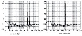
Figure of measured harmonics from paper illustrate what will be for "simple follower" or simple inverter without correction (left) and with correction (right) for the modulation depth of about 30% which is discussed.
A measutrement show THD of 0.15-0.2% and wide set of harmonics without correction.
Figure of measured harmonics from paper illustrate what will be for "simple follower" or simple inverter without correction (left) and with correction (right) for the modulation depth of about 30% which is discussed.
A measutrement show THD of 0.15-0.2% and wide set of harmonics without correction.
Attachments
Mikhail__K said:to Portlandmike
Figure of measured harmonics from paper illustrate what will be for "simple follower" or simple inverter without correction (left) and with correction (right) for the modulation depth of about 30% which is discussed.
A measutrement show THD of 0.15-0.2% and wide set of harmonics without correction.
So is the issue, effeciency?
What load do you want to drive.
My experience is that the current source loaded follower has much better performance than you show, both measured (beyond the limits of an Audio Precision system one or ATS-2) even when driving big loads, but big loads is relitive. Simulations are very good. I'd bias them to 10x of the max current required.
I simulated the proposed circuit (the 24V one) and a follower with +/-24V supplies. Ran the follower CS at 3mA and it smoked the darlington on distortion by 20dB or more.
Correction though, I didn't use a 0 ohm source, but a 5k source.
The distortion was present at the input, thus the main source is the input impedance. Perhaps you should use a buffer in front of it to deliver 0dB gain
Sorry, I'm sure I'm missing some point here, I just don't see its benifit. Is it that it has much higher drive? What is the target load? 50 ohms? Is it for a power amp stage? That might be useful then so you don't need to run it hard class A.
I'd be curious how you got your follower data to be so poor?
What was the current source? (or was it just a resistor
 )
)Gotta make the CS good, low gain, wide band, and reasonable compliance.
I did a simulation with the circuit I've favored and the results lay over the distortion of the input, and those are down >140dB as I recall (its on my other computer at work now.) Your circuit had good results, but still much much more 3rd harmonic. Down 90dB as I recall, but 3rd, not second. I think 2nd is free to most listeners, especially below a percent.
I've done a novel distortion cancelation circuit too, that worked very well at gains of 10 or more.
I'd like to read your paper, but didn't know what it opens with.
Can you give me a hint?
I'd attach graphs, but I have always had trouble with that. I'm a bit dim at some things.
Best Regards,
Mike
Hi, Mikhail,
I also got blocked by blackholes.easynet.nl.
I got this email on yahoo d_lumanauw@yahoo.com , but only 1Gb.
Hi Portlandmike,
I also got blocked by blackholes.easynet.nl.
I got this email on yahoo d_lumanauw@yahoo.com , but only 1Gb.
Hi Portlandmike,
Is it possible for us to see what it is?I've done a novel distortion cancelation circuit too, that worked very well at gains of 10 or more.
Originally posted by Portlandmike
...
I did a simulation with the circuit I've favored and the results lay over the distortion of the input, and those are down >140dB as I recall (its on my other computer at work now.)
...
I've done a novel distortion cancelation circuit too, that worked very well at gains of 10 or more.
...
I'd attach graphs, but I have always had trouble with that.
I'm a bit dim at some things.
Best Regards,
Mike
Dear Mr. Mike,
first of all thank you very much for your extremely kind and valuable information and advice.
I can only add that I am very eager to know something more about your topology.
Of course in case that you have any intention to disclose that information to us all.
Anyway, thank you so much again.
Kind regards,
beppe
- Status
- This old topic is closed. If you want to reopen this topic, contact a moderator using the "Report Post" button.
- Home
- Amplifiers
- Solid State
- Single darlington line preamp.