Originally posted by richie00boy
1) If you look at my website you can easily adapt the op-amp supply or the high voltage supply to your needs")
2) A 50V supply is not needed at all, 18V would be sufficient, but some component values would have to be scaled down.
3) The high voltage supply would fit in with your philosophy of minimal parts and has no loop feedback.
Dear Mr. Richie00boy,
1) Thank you sincerely for your valuable suggestion.
I will study your circuit in depth.
2) I must be completely honest: I do not even know how to start for scaling down components values.
I will stick with the 50V supply also because I want to set-up a good PS around that value to be used with other prototypes I have in mind and at hand (a Bride of Zen in my closet waiting for a better power supply).
3) Well to call it "philosophy" could sound presumptuos.
It is just that it intrigues me to see what can be obtained, in terms of sound, from very basic topologies.
On the basis of what I heard from a BOZ (1 mosfet line stage) and a 2 bjt preamp I am quite optimist.
It has become a sort of obsession maybe, but that is.
Also considering that many respectable audio designers have abandoned complex topologies in favour of simpler ones maybe doing a lot of efforts to optimize them.
Thank you again.
Regards,
beppe
I suggest you look at my high voltage differential supply then. Use the top half of the circuit only and make the following changes:
R1 220R 4W for 100R 2W
D1 BZX79C18 for a 51V type BZX79C51
R3 15k for 1.8k
R5 3.3k for 20k
Omit the LED and it's resistor
The input voltage of 60V is not critical, a 45V transformer (giving 62V when rectified) would be OK.
R1 220R 4W for 100R 2W
D1 BZX79C18 for a 51V type BZX79C51
R3 15k for 1.8k
R5 3.3k for 20k
Omit the LED and it's resistor
The input voltage of 60V is not critical, a 45V transformer (giving 62V when rectified) would be OK.
noname said:a very simple modification of Darlington with only one rsistor,
reduce THD 100-200 times -
from 0.2% to 0.001% measured.
It would be proper to note that this circuit was published in Russian magazine "Radio" (12-2005) by M. Kulish. Here is the first page of that article (djvu) :
x-pro
Attachments
noname said:a very simple modification of Darlington with only one rsistor,
reduce THD 100-200 times -
from 0.2% to 0.001% measured.
A big problem with that circuit
is that if you use one single darlington transistor, like BC372 in first simple example,
this circuit will be impossible.
You have to use 2 transistors, in a darlington arrangement.
There is a difference using one darlington transistor
instead of 2 transistors in darlington.
In first case you have not many choices to modify or add resistors.
This is one major reason, why one darlington
is ALMOST NEVER USED in high quality audio circuits.
Including power output stages.
Here is a bit more about that circuit:
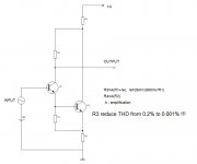
I've simulated the simplest circuit from that article in LTSpice. Here it is:
It is not a darlington as such, rather a two-transistor error-correcting circuit with a very good performance. In the next message I will attach the result of the simulation - FFT from "output 1" and "output 2" for 2 V p-p input/output.
x-pro
Attachments
x-pro said:Here is a bit more about that circuit:
I've simulated the simplest circuit from that article in LTSpice. Here it is:
It is not a darlington as such, rather a two-transistor error-correcting circuit with a very good performance. In the next message I will attach the result of the simulation - FFT from "output 1" and "output 2" for 2 V p-p input/output.
x-pro said:And this is the FFT graphs:
Is a dramatic improvement, taking output from point 2.
And the simulated response of output 2, is at real Hifi level low distortion.
Hi, Xpro,
Do you have a version of non-djvu for your post#24 attachment? My computer cannot view .djvu
Do you have idea how to implement this for push-pull / output stage?
Do you have a version of non-djvu for your post#24 attachment? My computer cannot view .djvu
I'm always interested in anything that contain words "Error Correction"It is not a darlington as such, rather a two-transistor error-correcting circuit with a very good performance.
Do you have idea how to implement this for push-pull / output stage?
Originally posted by x-pro
And this is the FFT graphs:
Dear Sir,
thank you so much for your extremely interesting posts.
In your experience how does the output from the sim programm compare with the real output on the oscilloscope?
Thank you very much again.
Kind regards,
beppe
Originally posted by lumanauw
Hi, Xpro,
Do you have a version of non-djvu for your post#24 attachment? My computer cannot view .djvu
Unfortunately, no.
I'm always interested in anything that contain words "Error Correction"
Do you have idea how to implement this for push-pull / output stage?
As this circuit idea works by summing currents it suits perfectly a voltage amplifier but not easy to implement in an output stage. Further in the article the author shows a completely symmetrical VAS producing very low distortion using the same error-correction idea. I'll try to attract his attention to this thread as he is active on one of the Russian DIY forums. I would prefer if he'll answer questions about this circuit.
x-pro
Hi,
it appears that the darlington configuration but taking out2 as the output is using the second transistor as a ccs.
Would similar results be obtainable if a real CCS was put into the emitter of either TR1 or even into both TRs or into the whole darlington emitter connection?
it appears that the darlington configuration but taking out2 as the output is using the second transistor as a ccs.
Would similar results be obtainable if a real CCS was put into the emitter of either TR1 or even into both TRs or into the whole darlington emitter connection?
x-pro said:
Unfortunately, no.
As this circuit idea works by summing currents it suits perfectly a voltage amplifier but not easy to implement in an output stage. Further in the article the author shows a completely symmetrical VAS producing very low distortion using the same error-correction idea. I'll try to attract his attention to this thread as he is active on one of the Russian DIY forums. I would prefer if he'll answer questions about this circuit.
x-pro
Dear Sir,
please excuse again my question.
In front of Q1 no resistors or caps are needed (to fix the base voltage) ?
I.e. is the schematic ready to build as it is ?
After your reply I will do it straight away.
I have been amazed by the sim results. Quite astonishing indeed.
Great topology!
Thank you very much again.
Kind regards,
beppe
beppe61 said:In your experience how does the output from the sim programm compare with the real output on the oscilloscope?
It usually gives you a good idea about behaviour of a circuit however there are many limitations especially in simple simulators and you shouldn't trust them too much.
x-pro
beppe61 said:In front of Q1 no resistors or caps are needed (to fix the base voltage) ?
I.e. is the schematic ready to build as it is ?
If you look carefully at my simulation circuit you'll see that V1 voltage source has 7V DC component. So the answer is: you'll need a proper DC biasing and coupling capacitors on the input and the output.
x-pro
Originally posted by x-pro
If you look carefully at my simulation circuit you'll see that V1 voltage source has 7V DC component.
So the answer is: you'll need a proper DC biasing and coupling capacitors on the input and the output.
x-pro
Dear Sir,
I have to tell you that my knowledge is very basic.
So I would need a confirmation on the following.
Do I have to put a voltage divider in front of Q1 to get 7V at the Q1 base and of course a nice input coupling cap ?
If the real output resembles even marginally to the V(out2) sim output I have found my new line stage !
I promise not to disturb you anymore.
Thank you very much.
Kind regards,
beppe
AndrewT said:Hi,
it appears that the darlington configuration but taking out2 as the output is using the second transistor as a ccs.
Would similar results be obtainable if a real CCS was put into the emitter of either TR1 or even into both TRs or into the whole darlington emitter connection?
Second transistor here is not CCS
. It is an error-correction circuit where one transistor provides most current and the second provides for a correction signal. The sum of two currents makes a corrected low-distortion output.x-pro
lumanauw said:Do you have a version of non-djvu for your post#24 attachment? My computer cannot view .djvu
The official djvu viewer is free, just Google for it.
Originally posted by x-pro
1) It usually gives you a good idea about behaviour of a circuit 2) however there are many limitations especially in simple simulators and you shouldn't trust them too much.
x-pro
In any case a very good way to start, I understand.
Thank you again.
Regards,
beppe
- Status
- This old topic is closed. If you want to reopen this topic, contact a moderator using the "Report Post" button.
- Home
- Amplifiers
- Solid State
- Single darlington line preamp.