that link takes me to the preceding post (14061).
Where did you intend that link to point?

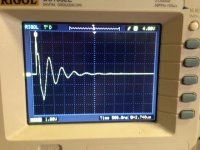
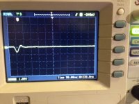
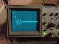
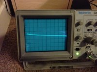
I posted the target snubber pic, if you use 500R the tx will be over damped and scope will show a large tail wave, if you use 220R you possibly see in the scope more than one wave or at least the second inversed wave.
Yes, thanks, i saw that, and I have looked at that other thread, but not read all of it. My question, though, is "How does the resonance of the secondary vary with the value of the resistor?". That is, how critical is the resistor value to the amount of ringing? How far from optimum still gives an improvement, and how much improvement do we lose as we vary from optimum?
I also realize those questions belong in the other thread, and I thank you for posting your measurements. Really helpful stuff!
Have a nice weekend Alex")
Hi Felipe,
One more opportunity to thank you. It wouldn't be possible without you.
I glad I have that jig. Requested data is coming soon.
Yes, thanks, i saw that, and I have looked at that other thread, but not read all of it. My question, though, is "How does the resonance of the secondary vary with the value of the resistor?". That is, how critical is the resistor value to the amount of ringing? How far from optimum still gives an improvement, and how much improvement do we lose as we vary from optimum?
I also realize those questions belong in the other thread, and I thank you for posting your measurements. Really helpful stuff!
You are asking subjective opinions, overdamped sounds bad and at this point I prefer without snubber, I can tell you the sounds improve more when more near is well damped the transformer without overdamp, I had a lot of fun playing with the jig.
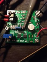
I also can do measurements with Quasimodo for all US located guys who use Antek toroids, the same tranys that I have in my builds:
AS-0515 - 50VA - 15V
AS-1236 - 100VA - 36V
AN-8412 - 800VA - 4x12V
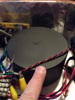
For all friends who use Antek "AS-1236 - 100VA - 36V" for FSP.
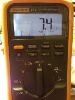
Cx=10nF, Cs=150nF and Rs=7.4R
Attachments
He is not asking for "subjective" opinion.
He is asking for measurements when the damping resistor is less than optimum.
What he said.
Hi all, hi Salas,
I am assembling one pre, I am looking forward to switching it on!
I have a question, by no means a critic, I just would like to learn more.
The problem arise when I try to select 4 red leds for the riaa: I can't find a set that gives 7,75V. I reach less than 7V (more like 6,9V) when measured with a BF245A with Idss of ~4,7mA. Ok, I think I can replace one (or more than one) red led with a green one. But...
If I look at the curves for a standar led, in order to reach a "linear" region, where the voltage changes only a little varying the current, I should use a higher current than 4-5mA. Is there any reason for not doing so?
Thank you for your great design, I will let you know my feelings after the realization!
The prototype's Leds were strong. Were giving more Vf than some other reds. If you got other to test or green or want to drive those you got with higher Idss Jfet so to push their Vf up the curve, its alright. 7.4V in total will also do. The voltage delta of each brand's type curve is not of interest because constant current is used.
- Home
- Source & Line
- Analogue Source
- Simplistic NJFET RIAA