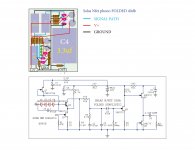
The sonic differences will be smaller for high output cartridges between the telescopic and folded cascode versions since the SNR is naturally stronger, but the FSP is still the better choice. Especially on its pcb that proved a success for absence of noises and good resolution. Not forgetting the positive contribution of its smack on integrated regs. The weaker resolving power of budget MM vs. expensive MC or MM will set a limit anyway. There is MM configuration in the FSP guide. If 2SK369BL are difficult for you, there is a 2SK170BL variation that I have suggested to member Roberto not too long ago and he had made on own boards. Here is it again. Should be kinda middle of the road compromise. It was for circa 8mA IDSS JFETs.
Almost ready to start up one channel of the attached schematic...
I've got a 16V 470uf cap on C8. I will be using 30V-ish rails. Is 16V for C8 enough voltage-wise? Should this be a 25V or 50V cap instead?
Almost ready to start up one channel of the attached schematic...
I've got a 16V 470uf cap on C8. I will be using 30V-ish rails. Is 16V for C8 enough voltage-wise? Should this be a 25V or 50V cap instead?
Oops. Schematic attached.
Attachments
Help needed MC/MM RIAA Phono Preamp
I want to build a MC/MM phono preamp based on the circuit posted by Salas on post #169
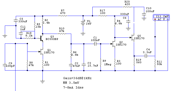
This circuit meets my expected gain and I already had some parts like the 2sk170 in the idss range, 3.3uf & 0.1uf Mundorf Caps, transformers and power supply for 24v, Dale RN resistors. It does not have a suitable MC input, so I add a MC stage based on the Boozhound Lab MC Pre-Pre, also for both inputs I had added a set of capacitive and/or resistive options that will be set using dip switches, the idea is to had support for a broad range of cartridges.
I had very limited electronics knowledge, I really don’t know if both circuits can be put together without making some component adjustments at the MC stage, so I will really appreciate if someone can review it and post some comments.
My questions are:
1) Is a single 2sk170 recommended for MC stage? Paralleling 2 or more will be better?
2) Which jfets should be matched?
3) At the MC input R26 will be optional, for a MC cartridge there is a need for a capacitive load like C16?
4) R22, R23 & C14 had suitable values for a 24v power supply?
5) The MC output load resistor (R25) and capacitor (C15) has appropriate values for 47K input load at the MM stage?
6) Is ok to use Nichicon KZ polarized electrolytic caps on C5, C6 & C10 on the MM stage and C14 on MC stage, any other brand/model suggested apart from Black Gate?
7) What type of cap is recommended for C11 on MM stage?
8) For C3 cap on MM stage I had read that is OK to use a 16nF value, what brands/models are recommended for this cap?
9) Which resistors that are most critical in terms of sound quality? I will use Dale RN, but maybe I can invest more on some other like Welwyn or other brands to get better results, any recommendation will be great.
I will really appreciate any comments, also I want to thanks to everyone that has posted all this valuable info here, specially to Salas for his great support.
Regards,
Alejandro
I want to build a MC/MM phono preamp based on the circuit posted by Salas on post #169
This circuit meets my expected gain and I already had some parts like the 2sk170 in the idss range, 3.3uf & 0.1uf Mundorf Caps, transformers and power supply for 24v, Dale RN resistors. It does not have a suitable MC input, so I add a MC stage based on the Boozhound Lab MC Pre-Pre, also for both inputs I had added a set of capacitive and/or resistive options that will be set using dip switches, the idea is to had support for a broad range of cartridges.
An externally hosted image should be here but it was not working when we last tested it.
I had very limited electronics knowledge, I really don’t know if both circuits can be put together without making some component adjustments at the MC stage, so I will really appreciate if someone can review it and post some comments.
My questions are:
1) Is a single 2sk170 recommended for MC stage? Paralleling 2 or more will be better?
2) Which jfets should be matched?
3) At the MC input R26 will be optional, for a MC cartridge there is a need for a capacitive load like C16?
4) R22, R23 & C14 had suitable values for a 24v power supply?
5) The MC output load resistor (R25) and capacitor (C15) has appropriate values for 47K input load at the MM stage?
6) Is ok to use Nichicon KZ polarized electrolytic caps on C5, C6 & C10 on the MM stage and C14 on MC stage, any other brand/model suggested apart from Black Gate?
7) What type of cap is recommended for C11 on MM stage?
8) For C3 cap on MM stage I had read that is OK to use a 16nF value, what brands/models are recommended for this cap?
9) Which resistors that are most critical in terms of sound quality? I will use Dale RN, but maybe I can invest more on some other like Welwyn or other brands to get better results, any recommendation will be great.
I will really appreciate any comments, also I want to thanks to everyone that has posted all this valuable info here, specially to Salas for his great support.
Regards,
Alejandro
Regards,
Alejandro
1. Don't expect great SNR.
2. Each one to its other channel brother
3. Not always necessary and curtailing bandwidth. Use R15, C16 only in case of instability.
4. R22, C14 are just an RC filter. R23 is load. If you copied from 24V rail spec circuit its OK.
5. Use 0.47uF C15
6. Matter of taste. KZ are popular capacitors as Silmic II are. Prefer the latter if there are bright elements in the rest of the system.
7. MKP 63V like Wima.
8. Vishay 1837 + Mica or styrene.
9. R10, R6, + your input load resistors of final most used value choice.
Good luck.
Four days i could not try anything because I had urgent job. Will continue as soon as I get some time.
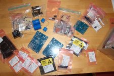
If Salas permit, I can show my single-layer pcb euro size 160x100mm
I would suggest you got a final theoretical with values that work well and sound good & quiet on confirmed cart output and gain in combination with your board first before some home etchers will follow your prototype. But no mechanized production files on open share please, only graphical, I don't want to see it offered on ebay by some pirate sooner or later.
1. Don't expect great SNR.
2. Each one to its other channel brother
3. Not always necessary and curtailing bandwidth. Use R15, C16 only in case of instability.
4. R22, C14 are just an RC filter. R23 is load. If you copied from 24V rail spec circuit its OK.
5. Use 0.47uF C15
6. Matter of taste. KZ are popular capacitors as Silmic II are. Prefer the latter if there are bright elements in the rest of the system.
7. MKP 63V like Wima.
8. Vishay 1837 + Mica or styrene.
9. R10, R6, + your input load resistors of final most used value choice.
Good luck.
Salas, thanks a lot you for your answers, I will redraw the schema, buy the parts I don't have and try to make a protoboard prototype.
Regards,
Alejandro
I wonder many things, like if our universe is endless and if there is any justice in this world. I also wonder if you guys think it is a good idea to cut the boards a bit and make room for those coolers? If so I would make holes in the chassie and a barrier to keep the heat out from the rest of the comps in the chassie. I have plentiful of thise coolers.
Attachments
I also wonder if you guys think it is a good idea to cut the boards a bit and make room for those coolers? If so I would make holes in the chassie and a barrier to keep the heat out from the rest of the comps in the chassie. I have plentiful of thise coolers.
I dont understand how cutting the boards helps.
I dont understand how cutting the boards helps.
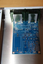
Those sinks are a tad larger and one-directional so I would get the heat out of the chassie and be able to EMI-seal the rest. I dont see any copper traces south of the mosfets. I would isolate the sinks from the chassie and between themselves.
Do you really expect to receive 2sk369BL from China?Some bits and peaces and a couple of hours. Still no 2SK369-BL from fleabay china. 30 degrees celsius. Soldering or beer, that is the question.
Do you really expect to receive 2sk369BL from China?
Dunno. Jungfang electronics something. Ordered 2*50. We'll see. Buzz, your my hero.
Stajo,
I know I never (when I had my boards semi-working) thought there was anything approaching excessive heat being generated by the MOSFETs.
I would think the heat from these is useful in maintaining the temperature in the box to keep the 369's stabilized. You might get more variation in temperature without these.
In addition I would not want to increase the path from the regulator to the circuit. Regulators loose goodness quickly the further they are from the circuit
Those are interesting sinks but I think you might be trying to challenge me in the "let's see how many things we can do differently" contest!
Take care,
Stajo,
"let's see how many things we can do differently" contest!
Take care,
Core DIY
Core DIY
You are a formidable competitor!
When there is no heat being generated inside the casing, then Ta = Internal temperature (Tint).Stajo,
I know I never (when I had my boards semi-working) thought there was anything approaching excessive heat being generated by the MOSFETs.
I would think the heat from these is useful in maintaining the temperature in the box to keep the 369's stabilized. You might get more variation in temperature without these........................
And:
Delta Ta = Delta Tint
If there is any heat dissipation inside the casing, then Tint must be greater than Ta and that requires that delta Tint > Delta Ta
Any and all internal heat generators will INCREASE the variation in temperature of the coolest internal components.
- Home
- Source & Line
- Analogue Source
- Simplistic NJFET RIAA