Since i couldnt find a proper size screwdriver to adjust the VTA, i thought about nezbleu's idea (thanks!) for a thicker cork mat and bought a 5mm thick cork sheet. Actually i figured i would need 4mm for proper VTA but 5mm was the nearest i could find.
The tonearm appears to be perfectly parallel to the vinyl surface, and the sound is more "relaxed". Drawback is that the tonearm in playing position is higher than the tonearm lift mechanism, so the needle always touches the vinyl surface.
I finally got around to making a cork mat. I used cork/neoprene gasket material, but the only thickness I could find locally was 1/16", which was too thin, so I built it up in layers. I made a top layer about 29cm diameter with a cut-out for the label area, and fixed that to a full-size layer with flexible silicone adhesive. I added another layer on the bottom, so 3/16" (about 4.8mm) but it wasn't quite high enough (the original Thorens mat is about 4mm thick), so I added a 4th layer on the bottom.
The result, in terms of VTA, was perfect, and it really cleaned up the high frequencies. However, I need to adjust the arm lift as well, as it won't quite lift the stylus clear (depending on record thickness and flatness), and the mat almost covers the spindle! So I think I will revert to no more than 3 layers, maybe just 2, and bite the bullet and modify the arm board to lower the back of the arm. That is slightly complicated because the arm board overlaps the top plate, so if I remove material from the bottom it will limit downward travel of the suspension. So definitely a weekend project, since I'll have to remove the tonearm. Sounded very nice though!
") (And yes, I included the 45RPM adaptor cutout in mine, although the thick mat is higher than the 45RPM adaptor anyway.)
(And yes, I included the 45RPM adaptor cutout in mine, although the thick mat is higher than the 45RPM adaptor anyway.)Do not have 1.2r for R5x.... would like to test one channel today... can I use 1r instead ?
You can use 1R for now but don't forget to put 1.2R in the end. It tunes it somehow better.
Output cap for my phono amp/application
Since I do not really understand how the two devices I want my FOLDED to drive (40K line stage for below 500, 10K power amp above in parallel) affect the effective input impedance - I am wondering if the 10K of the power amp affects the amount of capacitance I should use?
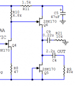
AND THEN I started wondering about having two output paths - a 0.22 uF cap (since I have a VCap of that value on hand) loaded by a 1M resistor which will be connected to the above 500 hz amplifier and a 2 to 3 uF cap loaded, also, with a 1M resistor connected to the below 500 line stage. Is there something I need to know that says I should not try this?
I figure I could use a less exotic cap for the line stage input which would come in handy since I have found the DUELUND 2.2 uF allows my FOSTEX T500s to sound better than they ever have. (everyone always talks about the "ping" sound of the T500s - with this cap I no longer hear the "ping") I had to give that a try since the phono stage is (blush) going so slowly. That cap is so huge it would be easier to have two output paths than that monster in the box.
All help is appreciated.
Thanks and take care,
Since I do not really understand how the two devices I want my FOLDED to drive (40K line stage for below 500, 10K power amp above in parallel) affect the effective input impedance - I am wondering if the 10K of the power amp affects the amount of capacitance I should use?
AND THEN I started wondering about having two output paths - a 0.22 uF cap (since I have a VCap of that value on hand) loaded by a 1M resistor which will be connected to the above 500 hz amplifier and a 2 to 3 uF cap loaded, also, with a 1M resistor connected to the below 500 line stage. Is there something I need to know that says I should not try this?
I figure I could use a less exotic cap for the line stage input which would come in handy since I have found the DUELUND 2.2 uF allows my FOSTEX T500s to sound better than they ever have. (everyone always talks about the "ping" sound of the T500s - with this cap I no longer hear the "ping") I had to give that a try since the phono stage is (blush) going so slowly. That cap is so huge it would be easier to have two output paths than that monster in the box.
All help is appreciated.
Thanks and take care,
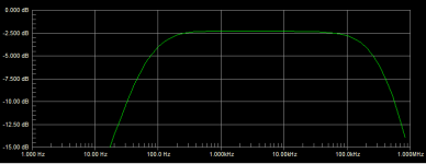
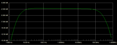
Here are the simulated frequency response effects if I got your query right. I only show the amps as output loads for simplicity since the extra 1M local terminations don't change the situation. High Out is from the 0.22uF & Low Out from the 2.2uF. High Out will affect your out of band low side crossover slope and phase. Has to be compensated in the scheme of things.Since I do not really understand how the two devices I want my FOLDED to drive (40K line stage for below 500, 10K power amp above in parallel) affect the effective input impedance - I am wondering if the 10K of the power amp affects the amount of capacitance I should use?
AND THEN I started wondering about having two output paths - a 0.22 uF cap (since I have a VCap of that value on hand) loaded by a 1M resistor which will be connected to the above 500 hz amplifier and a 2 to 3 uF cap loaded, also, with a 1M resistor connected to the below 500 line stage. Is there something I need to know that says I should not try this?
I figure I could use a less exotic cap for the line stage input which would come in handy since I have found the DUELUND 2.2 uF allows my FOSTEX T500s to sound better than they ever have. (everyone always talks about the "ping" sound of the T500s - with this cap I no longer hear the "ping") I had to give that a try since the phono stage is (blush) going so slowly. That cap is so huge it would be easier to have two output paths than that monster in the box.
All help is appreciated.
Thanks and take care,
Attachments
Hi guys,
I need to clarify one stupid doubt, I see the folded schematic and see that R1 is in paralell with the other four Rx resistors connected to the dip switch.
If I use other value, say 10k for Rx1 and set this switch to on (remaining 3 off), I will get the 10k in paralell with 47k for R1, correct? If so, this will mean I will get 8k25 if not mistaken, when I really need 10k, or other like 3k3, or whatever I choose for the others.
Shouldn't I move my naked Vishay 47k to Rx4 and leave R1 empty?
Thanks for the advice.
If you followed the guide's higher example values, they are thought out either as to keep the 47K R1 and create a set of possibilities with each position alone to it or with more in parallel, or not to use R1 and be what they are. You could also use a not super quality 1Meg for R1 to have a fixed reference to ground of no significant change to the paralleled, or any other value between 100K to 1Meg you may think gives you a preferable range of options. That would never leave the gate non referenced to ground by mistake if you plan to switch live (keep your volume low when doing that). Else don't switch load when the power is on and the cart is connected. Move out the naked Vishay very carefully with no grab or stress on its flat part if you will. Its a sensitive bug.
Just for giggles, here's the cork mat I made (think of it as a prototype).

I adjusted the cuing arm to work with it, but here's where I see a problem:

The spindle barely clears the record.
But it does good things for the VTA:

So now I have to decide whether to keep that mat (about 6.5mm thick) or change the arm board.
(Sorry Salas, I know this has nothing to do with the folded, but I have enjoyed using you as a sounding board while I work through this new setup.)
I adjusted the cuing arm to work with it, but here's where I see a problem:
The spindle barely clears the record.
But it does good things for the VTA:
So now I have to decide whether to keep that mat (about 6.5mm thick) or change the arm board.
(Sorry Salas, I know this has nothing to do with the folded, but I have enjoyed using you as a sounding board while I work through this new setup.)
If you followed the guide's higher example values, they are thought out either as to keep the 47K R1 and create a set of possibilities with each position alone to it or with more in parallel, or not to use R1 and be what they are. You could also use a not super quality 1Meg for R1 to have a fixed reference to ground of no significant change to the paralleled, or any other value between 100K to 1Meg you may think gives you a preferable range of options. That would never leave the gate non referenced to ground by mistake if you plan to switch live (keep your volume low when doing that). Else don't switch load when the power is on and the cart is connected. Move out the naked Vishay very carefully with no grab or stress on its flat part if you will. Its a sensitive bug.
Thanks Salas.
As always very clear.
So now I have to decide whether to keep that mat (about 6.5mm thick) or change the arm board.
(Sorry Salas, I know this has nothing to do with the folded, but I have enjoyed using you as a sounding board while I work through this new setup.)
It has to do a lot with the thread because its main goal is we try to maximize our vinyl experience with simple but effective means we all can understand and create.
The axis of this adventure is the FSP that treads on that path but any added value in understanding its mating cartridges and TTs with practical examples and unfolding stories is most welcome. When we started this thread five+ years ago the category was stagnating, now its flourishing with many more threads and this is heartening about vinyl replay related diy.
We don't seem to get serious problems in executing the FSP builds right by now, so we also try make the various vinyl rigs and FSP builds serve in a manner best suitable to each builder. What we know about the many fine things decisive on picking and setting a vinyl system right we contribute and surely someone will benefit. Even if our TT is a humble stock form second hand one, a diy flop or a diy masterpiece, or a top notch latest commercial one.
Could you spray paint that cork mat black, or that would change its surface damping negatively? Anyone who knows? Having the arm board modded is the more elegant solution visually in your case, I will tend to agree with you.
Also, guys if anyone is planning on getting a new TT with integrated arm think well about the height of the cartridge in mind. VTA is not a mere detail. Many are fixed for arm height. If planning on a new arm see it to have VTA adjuster else its a nuisance. Or know and plan a practical way of modifying its resting board height. Grab a good digital scale for VTF also. Vinyl replay is about small details to make it tick right. We see that proven once again in this tread frequently.
I did forget I would need two sets of the autoformers
Which makes the scheme something to think further about.
I do think you understand my idea.
Wondering if it could be better still to incorporate an even smaller cap to assist in keeping the low frequencies out of the compression driver.
Does one really want to set four controls for a change of volume? At this point I have no level control so I think I could live with it.
Thanks for your help.
(for level setting)Here are the simulated frequency response effects if I got your query right. I only show the amps as output loads for simplicity since the extra 1M local terminations don't change the situation. High Out is from the 0.22uF & Low Out from the 2.2uF. High Out will affect your out of band low side crossover slope and phase. Has to be compensated in the scheme of things.
Which makes the scheme something to think further about.
I do think you understand my idea.
Wondering if it could be better still to incorporate an even smaller cap to assist in keeping the low frequencies out of the compression driver.
Does one really want to set four controls for a change of volume? At this point I have no level control so I think I could live with it.
Thanks for your help.
- Home
- Source & Line
- Analogue Source
- Simplistic NJFET RIAA