The links in post n1 dont seem to be working corretly. All 3 links send me to the last page of the thread and not to the respective post.
I just tried them in Firefox on windows PC and they linked correctly. Either it was a glitch or try again from an alternative platform?
Is there a possibility the umbilical's shield connects to the main chassis and the psu chassis? Connect it to the main chassis only.
There is always a possibility, but in this case that was not the issue. I found the problem tonight. I have an RC filter on the incoming DC in the preamp chassis, on a pair of small perfboards. I had the incoming wires mounted very close to one corner of the perfboard, and a slightly oversized spacer under the board at each corner. The spacer was shorting V+ to the chassis! I removed the spacers and bodged something together with nuts and washers, and added some tape for good measure.
Powered up again, this time with the bulb tester, and everything looked good. Powered up each board, no smoke, raw DC was good, all LED's lit.
IT'S ALIVE!
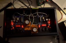
A little better photo:
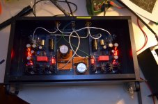
Here are the two chassis:
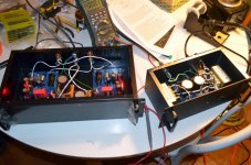
The PSU seems none the worse for wear after last night. Probably the dropping resistors limited the current somewhat.
Here's the interior of the PSU:
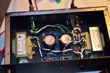
Here is the extra dropping R and filter cap in the folded chassis:
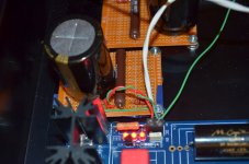
Voltages all look good so far, I will trim TP1/TP2 shortly.
I honestly don't know. The signal coax is a nice silver-plated copper, teflon dielectric I have been using for a while, I got it from a surplus place called Apex Junior (they are a vendor on DIYA). Military surplus is a good guess. The stuff for power is also from him, it's a nice Mil-Spec shielded twisted pair, not teflon, but M27500-22SD2T23 2. My umbilical is two lengths of that stuff in a techflex sheath, with the shields in contact with the connector body on the PSU end.
Oh, the irony of last night's drama is that the short was on the channel that I did NOT connect to the PSU -- that is, the PSU connected to the mini perfboard, but not to the amp. So I was monitoring the voltage on the OTHER board, when the power supply overheated (note to self: buy correct sized fuse!). So the board I was monitoring looked fine, while the other power supply channel had a short!
The hum/buzz is still present. I hope the new transformer from Hammond will be quiet. As I said, when I initially tested the xformers one was absolutely silent, the other didn't know the words so was humming.
The hum/buzz is still present. I hope the new transformer from Hammond will be quiet. As I said, when I initially tested the xformers one was absolutely silent, the other didn't know the words so was humming.
Is there a possibility the umbilical's shield connects to the main chassis and the psu chassis? Connect it to the main chassis only.
Hi. I can not see why it would be bad to earth both the psu and main chassis.
The umbilical feeds the amps with separate 0 and +. IF the main chassis was left floating there would be no need to connect the gnd pads on the amp boards.
My umbilicals shield ensures earth on both chassis. Maybe I have missunderstod something?
Regards
It is difficult to predict every failure mode.
Let's suppose that somehow mains gets on to one of the umbilical wires.
That wire feeds in to the next piece of audio equipment.
That piece of equipment is connected via a number of interconnects to other audio/visual equipment.
What blows the mains fuse in the faulty PSU that is feeding mains into one of the umbilical wires?
Every component that has any exposed conductive parts MUST be connected either directly or via a tested and approved Disconnecting Network to Protective Earth (PE).
This is the FINAL safety feature that blows the fuse in event of a mains fault.
BUT !!!!!
Double insulated (class2) components do not have a PE connection and by UK law must not be modified to include a PE connection. They do have exposed conductive parts and can transfer a Mains fault current through them to another item in the audio/visual chain.
That is a problem that appears to have got past the legislators.
Do not make the situation in your house worse by building any equipment with exposed conductive parts that is not connected to PE.
Hi again.
"IF the main chassis was left floating there would be no need to connect the gnd pads on the amp boards." Of course there is a need to give the amps ground if the designer says so - but from where should it be taken? PE as Andrew puts it? If so we either have to PE the chassis (for the reasons Andrew described above) or take GND from somewhere else (another wire). For my part the PE goes thru both chassis and doesn't stop before the 0/+ connections to the amps.
Please elaborate on this and tell me if I got it wrong.
Regards
As I understand it, Turbon, the raw supply chassis is grounded to PE. However, the 0-volts reference that is sent to the amp, or "audio ground" as some would call it, is isolated from that PE by the diodes || 10R resistor, and from PE and the other channel's 0-volts by a 1R resistor. That 0-volt reference should be the "ground" of the preamp circuit -- if you connect the preamp chassis to PE, then you should also isolate the 0-volt line from the chassis with a similar arrangement, else you will induce a hum voltage into the signal.
Hmm, Ok - the Folded_Simplistic_PCB_Guide.pdf tells us to:
"Connect the umbilical cable's shield only at one raw PSU's 0 point, cut its other shield end off."
So according to this the main chassis is left floating... The GND at C2x should be grounded - where? Obviously not the main chassis, maybe the 0 terminal?
Maybe the answer is as nezbleu described, another ying-yang arrangement is needed in the main chassis AND use the umbilicals shield as a PE connection.
Regards
Last edited:
- Home
- Source & Line
- Analogue Source
- Simplistic NJFET RIAA