They have excellent spec nonetheless. And they are counter inductance wound too. Its not that you can hear THE difference there but you will know it only after substituting with off the self general use resistors. Some unmistakeable extra finesse was there and poof... vanishes.
I've read that blog : http://www.diyaudio.com/forums/blogs/dvb-projekt/969-best-sounding-i-v-resistor.html
and i was curious to try them, plus it was cheaper buying directly from rhopoint than texas components. I will get some TNPW's some time in the future to compare against miniohm.
and i was curious to try them, plus it was cheaper buying directly from rhopoint than texas components. I will get some TNPW's some time in the future to compare against miniohm.
They were all selected for same idss originally, hence the same RDS? Its better the top buffer fet to be a bit stronger than the one at its tail.
Found the bug.... it was the ccs fet that went bunkers.
After removing it from the board I measured it with the peak and guess what.... it became a diode.... Cathode on the source and Anode on the gate.
Fortunately I have a list of all the parts of all my builds so I could replace the 6.5mA ccs fet by another one with the same Idss and Vp and now everything came to normal.
Note: It is good to match ALL parts so if you need to replace any, you know what clone to pick.
The buffer (follower) fet is stronger off course... at 7,5 ma
")
I've read that blog : http://www.diyaudio.com/forums/blogs/dvb-projekt/969-best-sounding-i-v-resistor.html
and i was curious to try them, plus it was cheaper buying directly from rhopoint than texas components. I will get some TNPW's some time in the future to compare against miniohm.
I/V is critical, but in this one we do here RIAA is critical. Maybe the impressions will happily correlate. But only experiments will show. Remember, if without an excellent cart and TT its a bit useless to go so deep into parts picking. It will still show but not as much worth it.
Did nothing at all.... one week ago I revamped my small outboard psu with one 100va double 30Vac secondary winding tx and plug it to the riaa... it worked fine during one week (left it on always) and that night something happened.... in the morning... no sound in the left channel.
I measured the psu output and got 40Vdc.... too low for the shunt giving out 35v... that is all.
What happens if the raw dc is too low to keep the shunt regulating ??? Does it stop regulating ?
I measured the psu output and got 40Vdc.... too low for the shunt giving out 35v... that is all.
What happens if the raw dc is too low to keep the shunt regulating ??? Does it stop regulating ?
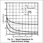
P.S. That is why I don't warn against if they have 33V B+ and high raw DC in this FSP PCB as long as they are OK with 9610 sink temperature and not higher than 50V for Q2x's safety, because 10V+ is good for the MOSFET. You see how pF evens out at VDS>15V and how it picks up at VDS<10V.
Attachments
So the mystery goes on
Anyway it is good to know simulating helps tracking possible causes and always keep track of all the values you use in every build (I am a controllership maniac)
Its not a mystery beyond you did not mess with it. Parts do fail randomly at times. You never know if there is a manufacturing % it will not get the same dissipation too well as the rest over time or some persistence with a wall iron, not a controlled station, weakened it during assembly. The wall powered irons are set at 400C+ so to retain some thermal capacity as they channel heat to the work and no control loop replenishes it. So they are too hot initially on small thermal masses.
I/V is critical, but in this one we do here RIAA is critical. Maybe the impressions will happily correlate. But only experiments will show. Remember, if without an excellent cart and TT its a bit useless to go so deep into parts picking. It will still show but not as much worth it.
That is true of course. I may went overboard with miniohm. My setup is this:
Pro-ject xpression 1 TT, with speedbox and Denon dl110 ( had dl160 but one channel went dead for no reason)
Myref RevC amp with premium parts
Triangle Heliad ES floorstanding speakers with upgraded crossover parts
I dont consider it to be a top system but it sure is nice sounding and musical
Im using a MF VLPS which i modded some time ago. Replaced stock opamps (5534) to opa627, Riaa capacitors to styroflex, riaa resistors to rc55y 0.1%, input electrolytic capacitors to BGNXhiQ, output elcap to BG N and powered by your v1.0 regulator. Sounds very nice and nothing like in its original form
P.S. That is why I don't warn against if they have 33V B+ and high raw DC in this FSP PCB as long as they are OK with 9610 sink temperature and not higher than 50V for Q2x's safety, because 10V+ is good for the MOSFET. You see how pF evens out at VDS>15V and how it picks up at VDS<10V.
Now this is some important notice
- Home
- Source & Line
- Analogue Source
- Simplistic NJFET RIAA