Thank you Salas,
yes my line stage input impedance is low 10K, I have here 1837 0,1 and 0,01uF, solen 0.1uF Film & Foil Polypropylene Capacitor, wima MKP10 0.01uf, wima FKP1 0.1uF, wima FKP1 0.01uF and obbligatto premium 0.1uF. Maxpou
I would suggest you try 4.7uF main capacitor value also for coupling to this 10K line stage.
Anyone able to compare this phono pre to the Pearl II?
Not so far for me
I had Simplistic (not standard) working on 2 Lead Acid Cells 24V nominal for a couple of weeks and I am truly impressed
Is a bit noisy but this may be due to my circuit and a rather riducusly HI gain
but this is just what I need for My F5.
I will takle noise issue later and I am shure it could be improved with better PCB lay out same serious screaning and so forth, Still I am working on the power suply for it (Salas Reflektor) once that is done I will start on Pearl II.
No point posting listening impression at the moment as I will ned to finish the PSU first
But so far realy truly impressed is a realy solid performer toe tapping guarantee Mylar films on RIAA made it much more musicall if compared to Poliester Film.
I had the impression that Green LED sounded beter than the RED ones (1.7V and 1.9V respect.) so I vill have to go back on it.
Mundorf Supreme are setled in and after a week sound is more defined with much beter resolution.
I Was wondering if others here have tried to change components as I did with same or maybe totaly opposite impressions?
Component wise as Reflecktor + Simplistic have quite a few components in comon with PearlII why not build both and try?
Last edited:
*Rumble
Yes *Rumble
But then if you actualy build things and actualy have a record player and actualy listen to music it all came clear...
Back on the Salas RIAA project
Finally, I'm back on building my RIAA after an 8 month hiatus. Just got components in, I'm starting to layout on vector board.
I have a nice long piece of blue vector board already. Is there any good reason NOT to have the shunt (1.2R) right next to the RIAA, apart from layout flexibility?
Next to each other, I can make the force/sense wires very short- ~ 3" max.
Cheers- Kent
Cool!
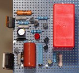
Attached is my test layout on vector board. I am assuming it's OK to use 121 ohms for R2, R3 & R7?
R11 is supposed to be 47K, just changed it. I read from Merlin C1 is crucial for good sound. I have some Wima MKP 4.7uf, laying about; that's the big red cap to the right. The other 4.7uf (C3) is a Panasonic Polypropylene 667-ECW-F2W475JA. Would these be OK for C1 as well?
~3" x ~2.4" (75 x 64 mm) footprint, nice and compact.
Attachments
OK, will keep C1 MKP and C3 Panasonic. Thanks Salas!
If I can borrow your eyes, here is the final layout for standard 0.1" hole spacing vector board. I've checked it over but might have missed something.
No PS built yet, I'll be powering it up with my bench supply, monitoring current and scoping for oscillation.
What's the best load to test the shunt? I figured 250R..?
Cheers- Kent
Attachments
- Home
- Source & Line
- Analogue Source
- Simplistic NJFET RIAA