Tanks Salas
I am measuring circuit as you kindly posted for me on 6832.
I will need to dig out Anti RIAA circuit.
OF top of my head it is the one with 1.91 K 511K 42sometink K 536R and 60R
MM input was taken at top of 536R MC at top of 60R 40 and 60 dB attenuation
Sorry I am so very untidy I had that in front of me for past 3 years and now that I need it again I can't find it
I will post exactly the circuit and source where I got it from as soon as I find it
In mean time have a couple of links
http://www.audioxpress.com/magsdirx/ax/addenda/media/colin2808.pdf
RIAA backgrounder 6 - Reverse RIAA
I have stuffed the boards with the MC prepre components as on SCH attached.
I have tried to increase gain at first with extra 2SK170s and it did help a bit then placed a pot in series with R1.
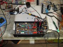
It is all still on the bench unscreened and such some how I know already that this is going to stay in the box for a long time once finished.
The RIAA prepre page from your write up
On the board a 150R 3W instead of the 7809 supplied by the 24 V rail
Gain after passive RIAA attenuation (60 dB) with 4 parallel 2SKS R1 =200R
It was 180 on your drawing
And Gain with R1=750R (using a 10 turn 1 K pot)
The source resistors are 33R again is what I have at the movement
Please remember that (for all in general) that I do not have much of a clue on what I am doing so it is easier to put same extra track and holes on the PCB and get rid of it later.
The amazing thing is that it worked the first time.
If once built the changes I have made sound fine I am thinking of little ladder attenuator and Simplistic ploughed in directly on my F5
I normally use only 4 maybe 5 volume settings as follows
Neighbours in
Neighbours out
Her out
And Mental
Straight Lipshitz?
You mean no Numan pole?
Load of controversy about that.
"Poor" Dude place a filter in one of his best selling lates (to stop cutting arm fliing off) and a week later....
A frequency he used was different to start with and 12 dB slope.
B different cutting late had different filters.
At the moment I am realy impressed with the shape of the Square
RIAA acuracy came later with loads of series paralel combination on Resistor and Caps.
You needed to tweak R1 higher on pre-pre because you degenerated by 33R each. That cuts on total Ygfs. Also adds 8.25R noise source against having just double 7mA ones without Rs. More or less amounts to the same noise performance with that and 4 fets, but eases fet matching a lot. If the signal was higher there, it could have THD benefit using the resistors, but not at 5mV pre-pre output level. The 150R resistor instead of own chip reg is rather OK since its fed from regulated supply and you retained the Cmult and 1mF R1 bypass. You will see for psu arrangements and pcb success by evaluating hum and hiss levels later when boxed up and properly grounded. Having 60dB spot on is the spec, you hit that, you may match that gain channel to channel by your pre-pre R1 trimmer, but check that the 40dB input is also matching by channel if to use MM cart in case you have different gain fets there since no selection was done you mentioned I think. The MM CCT's high Rs will ameliorate differences though. 100kHz start drooping is also the correct spec. Adequate for records and open-loop IMHO. You met that also. Although you hit a nice clean 15V pk-pk sine wave driving with the generator, I don't think that you can get enough level for ''her out'' and ''mental'' stages with just cartridges and direct to F5, since its a low gain amp. No ''lost constant'' in my Riaa, did not like it in majority of my records. 1.91k smells ''lost constant'' anti-riaa BTW. No big deal. So far so nice, congrats.
Tanks Salas
Still loads of work to do but considering how far I managed to get in a few hours I am shure it will be a realy nice sounding project.
As a starting point I will try to change the 33R and get rid of Jhonson noise there.
It does loock/feels beter than the LT1028 INA and split passive RIAA I made and was using before.
I am looking forward to stuf the second chanel and let it play while I make new PCB and get beter caps.
On the last picture I posted with R1 (MC part)=750R I got nearly 4 V out
At mental Volume (start to fill Bass in my tummy) I am asking the F5 to pump out only
12V and F5 has gain of 15 so I am confident that it will hit "her out" levels whitout any problems.
I will post a bit more about the Lead Acid batery suply I got 2 2.3Ah and most probably I can get a couple of days worth of pure bliss whitout recharge.
The $1M question is with how many mV input you got 4VRMS out though. 60dB produces 500mV from a 0.5mV cart like your MC. Much more gain would lead to noticeable THD & hiss.
P.S. Try with 4x 10R Rs in the pre-pre and adjust your shared drains load for 20dB gain. 60dB total when connected to the main circuit.
P.S. Try with 4x 10R Rs in the pre-pre and adjust your shared drains load for 20dB gain. 60dB total when connected to the main circuit.
Same as all troug pictures 1 V in Inverse RIAA 1V out top of scope input before inverse RIAA Filter both knobs set at 1V division
with 750R nearly 4 volts (now that is where I normaly get things vong) peack to peack
Yes10 R is just what I was thinking about briliant..
Bobo time for me ...
with 750R nearly 4 volts (now that is where I normaly get things vong) peack to peack
Yes10 R is just what I was thinking about briliant..
Bobo time for me ...
That is 63dB gain if you used the -60dB anti-riaa output. Pk-Pk was the $1M answer. You either pushed the pre-pre to 23dB, easy with 4 Jfets and trimmer load, or you got some hot Jfets in the main unit. That is a permissible gain along with pre-pre, as mentioned in the PDF, and done before. See channels are RMS out matched, check that it won't congest on your cart when playing records at that gain, some are very dynamic in transients, and that you like the Riaa shape in your system. Now its textbook flat. If your cart and TT set up is recently inspected for good balance, judge if you need anything else tonal wise by adding a little HF droop or not (+pF on C3), before you make an expensive parts unit as you said, provided you like the whole test phono of course. What is your speakers SPL/2.83V BTW? I still recommend you make its shunt PSU also, so to listen to it as originally intended.
Hi Salas
Just up now and ready to get craking
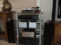
I have a pair of Polk LS15i they are nominal 87 dB and 4 homs the Room is 3 X 7 meters
with speakers at narow end.
Poor combination for the 1042 better for Elite.
So I do not need to much power and I like to listen at lower level (Disco years way past for me).
With the Elite (MC) I was thinking about dropping HF so tanks for that a rumble Filter may also be worth considering.
PSU is certanly in need off overhaul It is pretty quiet beeing 2 bateries
They do still have Jhonson noise and did not feel like using litium (less noise)
as sometimes those explode.
But now that I am ready to move away from the 8 legged kind I will need to take in to account the fact that the voltagge changes between 27 (fully charged cells) to 24V (50% Charge)
IS out of topic here but I have enclosed SCH of the batery Charger
It may be andy for some one, main bit is the Charger made with a LM317 and one transistor
Just up now and ready to get craking
I have a pair of Polk LS15i they are nominal 87 dB and 4 homs the Room is 3 X 7 meters
with speakers at narow end.
Poor combination for the 1042 better for Elite.
So I do not need to much power and I like to listen at lower level (Disco years way past for me).
With the Elite (MC) I was thinking about dropping HF so tanks for that a rumble Filter may also be worth considering.
PSU is certanly in need off overhaul It is pretty quiet beeing 2 bateries
They do still have Jhonson noise and did not feel like using litium (less noise)
as sometimes those explode.
But now that I am ready to move away from the 8 legged kind I will need to take in to account the fact that the voltagge changes between 27 (fully charged cells) to 24V (50% Charge)
IS out of topic here but I have enclosed SCH of the batery Charger
It may be andy for some one, main bit is the Charger made with a LM317 and one transistor
Attachments
And when one is not looking for sometink....
www.hagtech.com/pdf/riaa.pdf
On Reference RIAA Networks Jim Hagherman
Fig 6 Modified inverse RIAA circuit
is the one I use as inverse RIAA
www.hagtech.com/pdf/riaa.pdf
On Reference RIAA Networks Jim Hagherman
Fig 6 Modified inverse RIAA circuit
is the one I use as inverse RIAA
It is alive.
Second chanel stuffed and in the box
And plaiing away
Bit of 50 Hz mains with SS1 at 11 (Stuck with that while I wait for someting beter).
(I need to remake a few cables and cut off a few screens returns Other RIAA was balanced)
I am quite happy with sound already realy fluid and musical a bit less analitic than previous one I had. (and for this maybe even better as I had same poor records I could not longher listen to EG Live Cult Box set)
Going out for the day (prety pronto Her volume is already at 14:00)
and no much point being back till new PCB components are sorted
For a couple of Days work I am realy pleased.
Worth making and spending money on it now that I heard it absolutley YESSSS
Tanks Salas
By knowing how it sounds on batteries, first priority is PSU, needs specialized 24V supplies IMO. Two like this one won't cost too much to make. One 3.1-3.4 C/W upright PCB type TO-220 sink per Mosfet and will be good to go. Don't skip the 4 wire Kelvin output connection to load as depicted.
Attachments
It is alive.
Second chanel stuffed and in the box
And plaiing away
Sorry pictures lost on my previous posting
Back to day Job tomorow so thing are going to be much slower,IMO the potential for it to be a realy nice MC are all there.
I realy enjoied putting this togheter and results are well worth the effort of the past 2 days
Sound wise already very fluid and musical I have very litle if any hiss that would normaly be there in a noisy stage at this gain.
Tanks Salas and Ricardo
Attachments
Many would say different but I would suggest you give it a go at 1K load first.
Should I try first with 1k?. How can I understand if this value is ok?. Can I measure it and find this right resistor or it's just a "ear mater"?
On your circuit copy I have already mentioned 470R or 1K load for 103 classic 40 Ohm model. There is controversy among users, because many followed the 100 Ohm minimum on manual, few tried other. Its a matter of taste in your system. Still technically, a 40 Ohm coil must not be loaded less than 10X its value, so to give almost full output. You can put two pins on the pcb instead of a fixed resistor, and be able to solder different load resistors easily on those pins to listen and decide.
- Home
- Source & Line
- Analogue Source
- Simplistic NJFET RIAA