Using the calc. for an input impedance of 10K 1uF cutoff/corner frecuency 15.92Hz time constant 9.997us & 1.5uF cutoff/corner frecuency 10.61Hz time constant 15.000us, are my calculations right? what about the phase it's right?
That calc is right by all means. About phase, we are not dealing with rumble free USB servers here to go flat to DC without nasties, so the general idea is to keep the corner frequency as low as no gross over excursions occur with a given TT set up and speakers, helping to keep the phase as linear in the audio band's low region as it can be. 2nd or third order filtering I would not prefer though, unless there is strong need.
Please explain what do you mean by turning the phase early.
I know that we are wasting precious power just moving the woofer without producing any sounds but I know little about phase issues.
So using smaller output caps turns phase earlier.... there must be a sweet point if I get the general idea right ?
The 'sweet spot' in any system is to battle best what does the most damage first IMHO. If there is problem with rumble, say because the arm resonance is low and average disc is slightly warped, you fix that first by filtering if not to change cart. If you have closed box stiff suspension bass system and big amp, maybe not, depends. The recommended 2.2uF output cap is to make sure that the phono can relay bass well even when hooked up on an LSPD DCB1 or alike low impedance preamps. If you are sure a build will never be interfaced under 20K line input, you can use 1uF for instance. If there is no problem with excursions in given systems (as it seems the norm to be from all those applications reported here) prefer the 2.2uF. With 6u8, 47k, and underdamped reflex speakers, it surely went looking for trouble.
Chinese on Epay!!!!! I wanted the French but they were BIG bucks to get them here and I don't read/or speak Fench very well so their web site was a bit difficult. Before I committed to the R-core I wanted to try the cheaper ones first.
In reality they are right on spec for the size, just smaller than than the ones you are using. They are 2x18v secondaries and 30VA. When driving two channels it did fine but just was a little short of the voltage I wanted. With a single channel they were spot on.
I don't plan on putting it in a single box anymore. None the less I will run shielded mains and secondary wires. I put ferrite rings on the mains right at the trany as well. You can see them in the first picture of post 5509.
I like this time of year as I get a little down time from work and can focus. Starting to complete a few of the project lists I have for the simplistic.
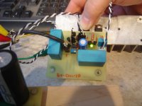
Attached are photo's of the new power supply and V1.2R for my simplistic. After a brief break to play with some of my kids gifts, I am going to breadboard it and fire it up.
Hi Sgregory
Really like your psu.
Are the Nichicon 3300u after the nippon caps ?
Would you post a schematic ? I am majoring in psu voicing and this info is very important.
What is the values of the Nippon caps ?
Ricardo
I will post a schematic shortly. Right now I am majoring in trouble shooting as I can't seem to get the V1.2R to light up properly. It seems that Q5 is full on dropping the rail to 1 volt.
The caps are slightly mixed. It is a R1 C1 L1 C2 L2 C3 filter.
R1 = 2R2
C1 = Nippon 6800uF + 3300 Nichicon
L1 = 1.5mH Hash Choke (ferrite Core)
C2 = 1000pF Mica
L2 = 1.5 mH Hash Choke (ferrite Core)
C3 = Nippon 12000uF + 2x 3300uF Nichicon.
I will replace L2 at some point with an iron core of higher value. I left room on the board for that. I do like the hash filter that Eli Dutman has been pushing.
I am considering to make a seperate rectifier board that RC bypasses the diodes.
Trouble Shooting Complete. I have no idea how the error checking routine in eagle allowed me to have a trace error, but it did. Once I corrected it in the software it wouldn't let me redo it? Go figure. My error. Anyhow after a little cosmetic surgery on the board, I now have two V1.2R's up and ready for install.
They hold voltage very well and have no hint of oscilation under resistive simulated load.
Now to install them....
They hold voltage very well and have no hint of oscilation under resistive simulated load.
Now to install them....
Attachments
The sink on the error amp BJT is a good reason it holds voltage well.") Amusingly, the loop gain simulation shows it on the verge of oscillation, as I have shown in the regs thread. When everybody who have copied the 1.2R by now has it working easier than 1.2 on first attempt layout. Its nice I did the mods before I analysed them, bcs otherwise I would have skipped it. Its likely that the real parts and layout behave differently enough. Repeatable so far in a positive way in this case.
Amusingly, the loop gain simulation shows it on the verge of oscillation, as I have shown in the regs thread. When everybody who have copied the 1.2R by now has it working easier than 1.2 on first attempt layout. Its nice I did the mods before I analysed them, bcs otherwise I would have skipped it. Its likely that the real parts and layout behave differently enough. Repeatable so far in a positive way in this case.
Amusingly, the loop gain simulation shows it on the verge of oscillation, as I have shown in the regs thread. When everybody who have copied the 1.2R by now has it working easier than 1.2 on first attempt layout. Its nice I did the mods before I analysed them, bcs otherwise I would have skipped it. Its likely that the real parts and layout behave differently enough. Repeatable so far in a positive way in this case.It certainly shows no issue of oscilation. My V1.2 was a bear if you recall and had to increase the gate resistor to get it to stop. In this case it was only my errors that prevented a perfect start-up.
FYI, I was able to dial the voltage from 14Volts to 54Volts. In all cases it was stable.
FYI, I was able to dial the voltage from 14Volts to 54Volts. In all cases it was stable.
 Lets hope it is going to be better suitable in your system too, because 1.2 original you already have is different, but no slouch either. Still if 1.2R will not be your preference, 2 extra, good quality variable regs, will not be enjoying much idle time in a drawer most likely. They will find hosts.
maxpou,
With a 36Vac through a CLC or similar filter, you should have plenty of voltage. Probably some Voltagw to burn off if it is high enough VA rated. I am using a 2 x 0-18V in series for mine an can easily obtain 45V under full load.
Salas,
You are correct. Regardless of which one I choose, the other will have a home soon enough. I even see a future for the original V1.0! Do I hear DAC????
Last edited:
Merlin,
Unfortunatley, It has been awhile since I listened to the V1.0 and it is not a simple process to change back to v1.0 now. I have had some major changes in my table and carridge since I used the v1.0 as well that even makes my notes invalid for a comparison.
I promise that one day I will put them in or build another RIAA for a second tone arm and compare.
Putting the 103R on this arm is something that I wanted to do. I will wait until I get the Nanook arm up and running to do it however. For Me with 10 thumbs for fingers, installing a cartridge is nerve racking.
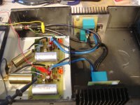
In the meantime, letting the system warm-up to give a serious listen. The V1.2R lives in its new home. The RIAA head amp is dead quite even at full volume. I was a little concerned at first until I cleaned the stylus ;-).
In the meantime, letting the system warm-up to give a serious listen. The V1.2R lives in its new home. The RIAA head amp is dead quite even at full volume. I was a little concerned at first until I cleaned the stylus ;-).
Attachments
- Home
- Source & Line
- Analogue Source
- Simplistic NJFET RIAA