Salas
Xpovia Polla !!!
Also attached is a copy of the new document that I'm working on. IT'S STILL A Beta. Any suggestion are welcomed
Pete
Its not a Beta any more. I have changed many things and its ready. I am uploading here, deleting the Beta not to remain and confuse, and also putting it in the evolution link from post #1. Thanks for the effort Pete, once more. Everything needed is in this document.
Attachments
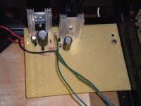
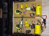
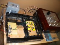
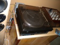
here are a few shots of my build. it is the earlier version of the regulator. moving the power supply to a separate box fixed the hum. dead quiet, not quite but quieter than the back round noise when the needle is on the record. This sounds good enough to make me take a hard look at some other parts of my system. thanks again to all. Evan
Attachments
The circuit is 41 db gain it runs on 25 volts. I have an adcom cross coil cart. I believe the output is 2.5 mv. There is more then enough gain for the rest of the system. Is there much improvement with the latest version regulator? a question on the riaa circuit the .1 uF cap that is place right after the voltage input seems to be bypassing the filter cap in the power supply. Should this cap be with the power supply or the riaa board?
Thanks for the encouragement, Evan
Thanks for the encouragement, Evan
Its not a Beta any more. I have changed many things and its ready. I am uploading here, deleting the Beta not to remain and confuse, and also putting it in the evolution link from post #1. Thanks for the effort Pete, once more. Everything needed is in this document.
Q5 vs Q6...

The circuit is 41 db gain it runs on 25 volts. I have an adcom cross coil cart. I believe the output is 2.5 mv. There is more then enough gain for the rest of the system. Is there much improvement with the latest version regulator? a question on the riaa circuit the .1 uF cap that is place right after the voltage input seems to be bypassing the filter cap in the power supply. Should this cap be with the power supply or the riaa board?
Thanks for the encouragement, Evan
Yes now I remember, you mentioned the cross coil in a recent post. The gain for that cart is OK. The PSU in the PDF is the same class except it can be variable for not showing two schematics, and being 4 wire Kelvin. A difference is your Zener, when there is a trimmer pot in that one, but having big FC cap shunting the Zener surely kills its noise. Is it 1000uF? The 0.1u was meant local to the phono, when there is long wire like in your case. So to battle the inductance. What can have a chance for even better sound, is to follow the 4 wire arrangement. It can be done in yours as well, if you will take a good look in the arrangement of the one in the PDF.
I found eveything perfect apart from that.
I must ask again.... I see you selected a 470u for C6.... is it better than your previous choice of 220u in other designs ?
Also in your previous designs there was no C5 and Q2 + line was filtered with a cap... would you explain the differences ?
I must ask again.... I see you selected a 470u for C6.... is it better than your previous choice of 220u in other designs ?
Also in your previous designs there was no C5 and Q2 + line was filtered with a cap... would you explain the differences ?
Changed the .zip. Ricardo please download and check if it opens OK and if all is in order. I put Q5 on the schematic. The transistors are 5 anyway. Now your questions. With so big resistors for RC the other lower caps were enough. I just thought that in most good capacitor ranges 470uF has less ESR than 220uF, when it is not that bigger or more expensive, and even it can make for a better price when buying all in one type. Buying the 16V one at 35V or 50V too will not hurt. So that is why. RC filter I added as a good measure for maybe not so great line noise in each possible build, because its a general recommendation document.
my first HiFi was all Mcintosh Handed down from my fatherinlaw. A pair of mc 30s and c8 preamps rigged to run off one volume control. This sounded nice, but at one point we needed the money more then the stereo so it was all sold. Lately I have been listening through a hafler iris driving solid state amps. I built an akaido tube preamplifier and needed a phone preamplifier to make it complete. This has been a lot of fun to build not to complex and great results.

evanc,
I know that feeling of money vs. stereo thing. Many years ago, I was riding high on youth with all CJ premeir equipment and Theil speakers. Life changes that. Like you, I am having more enjoyment building and learning with outstanding results. The simplistic njfet is a prime example.
I know that feeling of money vs. stereo thing. Many years ago, I was riding high on youth with all CJ premeir equipment and Theil speakers. Life changes that. Like you, I am having more enjoyment building and learning with outstanding results. The simplistic njfet is a prime example.
Hi Salas
The zip works fine ... thank you for the correction... sometimes a small typo can induce people (like me) in error.
I will try the bigger cap over the leds and report the differences.
I already reported that one of my builds has much lower noise than the others. I went back and saw that I am using a 330u BG there instead of the "normal" 220u ZA. Maybe it is responsible by reducing noise floor.
Much difference only from that is a bit weird. Don't know if different types's impedance can do something with the way it shunts the 550's base, more than the actual value. Also not all K170s have the same noise in any batch. You could have hit on a noisier input stage one, provided all other things have been kept equal between the builds you refer to.
Hi Salas
The zip works fine ... thank you for the correction... sometimes a small typo can induce people (like me) in error.
I will try the bigger cap over the leds and report the differences.
I already reported that one of my builds has much lower noise than the others. I went back and saw that I am using a 330u BG there instead of the "normal" 220u ZA. Maybe it is responsible by reducing noise floor.
The real test was with the same amount of capacitance but always BG have "magic" sucess
- Home
- Source & Line
- Analogue Source
- Simplistic NJFET RIAA