Coax really matters when we are using TT.
My system is hum free but I experienced some trouble with hum in my previous systems.
Fo instance, before CD appeared (my first one was a Sony CDP1) I was allreday determined to mod everything so I decided to "improve" my B&O tangencial tonearm TT by replacing the 5pin din outputs by RCA so I could use better cables.
While I was at it, I did not know about coax virtues so I used unshielded high purity copper inside the TT connecting the cart to the RCA. Those wires had 5cm max lenght and the hum was unbearable.....
Recently I tryed my CD cables (Nordost flat unscreened) in my TT and while I get some speed improvements, I can not avoid the hum.
Now I am using some silver VDH cables (screened) on the TT and it is sounding wonderfull.
You progress looks good Lee
Ricardo
I didn't replace any wires with coax. But as an experiment I did wrap the internal wires in the preamp with copper foil and ground that. It has seemed to help. The arm is now grounded also with a length of wire to the phono stage, which helped massively.
I will figure some way of shielding the remaining wire soon. I rewired the tonearm (an SME Series III) with high purity copper litz cable. This is silk insulated and was a good improvement on the original wire. The single lengths run right from the cartridge pins to the phono input of the pre/phono stage. I believe once I move the nasty transformer out of the TT into a separate box, and feed regulated power to the TT the hum will have gone completely.
I will also be attempting to adapt the phono stage board layout I did to accommodate these rather large Russian Military Silver Mica and paper in oil caps. Thanks for the nice hint there Salas, they seem to sound great even without burn-in.
Regards, Lee.
Hi Salas. I've done as much listening as I could, but I've not had time to test the shunt yet!
I am getting some distortion on vocals, which I assume is down to the cart mis-tracking, as it only seems to be on vocals. There is some sibilance on treble sounds too. I will re-align with a different template later on today, and once the Christmas tree is up, I'll have a go with the shunt reg too.
Cheers, Lee.
The arm is a SME Series III, and the cart is a Grado Prestige with a Prestige Gold stylus.
I have rewired the arm and added some mass to the arm with Blu-tak and a 5 pence coin on the headshell, lol. I started a thread asking for mods advice about this arm here
I need a new arm I think, but funds are very tight so it'll have to wait.
Lee.
I have rewired the arm and added some mass to the arm with Blu-tak and a 5 pence coin on the headshell, lol. I started a thread asking for mods advice about this arm here
I need a new arm I think, but funds are very tight so it'll have to wait.
Lee.
gone mine running..
...and it works! Can't listen too much- neighbors won't like it at 4:30 AM!") I built Sala's 56db gain one on post 110.
I built Sala's 56db gain one on post 110.
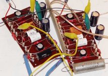
Of the 2SK170's I got, the best 4 were all 8-8.16 mA Idss. Used PRP resistors throughout. Siemens ps for 47n Laclanche ps for the 100n, and Multicaps for the 16n. All the parts were better than 1% except for the multicaps, they were all over the place.
El chepo 'lytics I had on hand for the 470uF. I used a Solen and a Vitamin Q for the 1.5uF output couplers. I have more of the vit Q's so that will go in. Solen sounds 'tizzy' on first impression.
Built on old turret boards- tube style!
Using four 9v batteries as the PS parts have not arrived. It's an alligator dog mess at this point, but sure sounds great! Quiet! Airy! Bit thin on the bass.
Salas, I set my trimmers all to 40 ohms. How do I measure the Idss in circuit? I'm a big newbie to silicon. One board pulls 8.5mA; the other 8.6mA. That sound right?
To think of the tubes I would have to go thru to find quiet ones.... this is so much easier. Now for the break in. Tomorrow.
Thank you, Salas! 
-Kent
...and it works! Can't listen too much- neighbors won't like it at 4:30 AM!
I built Sala's 56db gain one on post 110.Of the 2SK170's I got, the best 4 were all 8-8.16 mA Idss. Used PRP resistors throughout. Siemens ps for 47n Laclanche ps for the 100n, and Multicaps for the 16n. All the parts were better than 1% except for the multicaps, they were all over the place.
El chepo 'lytics I had on hand for the 470uF. I used a Solen and a Vitamin Q for the 1.5uF output couplers. I have more of the vit Q's so that will go in. Solen sounds 'tizzy' on first impression.
Built on old turret boards- tube style!
Using four 9v batteries as the PS parts have not arrived. It's an alligator dog mess at this point, but sure sounds great! Quiet! Airy! Bit thin on the bass.
Salas, I set my trimmers all to 40 ohms. How do I measure the Idss in circuit? I'm a big newbie to silicon. One board pulls 8.5mA; the other 8.6mA. That sound right?
To think of the tubes I would have to go thru to find quiet ones.... this is so much easier. Now for the break in. Tomorrow.
Thank you, Salas!
-Kent
Attachments
Hi Kent,
You just adjust the source trimmers so to read 8.1V on top of every FET where it meets its load resistor. There is no such thing like in circuit Idss. Its just that the stronger the FETS for Idss are, the stronger they pull current in a given circuit and the stronger they gain. If you equalize the voltages you will be OK.
I hope that you are not driving an impedance under 50kOhm and you notice lean bass just because you did not employ an additional buffer stage and/or the output capacitors are rather small for what you drive.
Otherwise, the somehow thin bass must be due to 9V batteries and alligator clips. Much added PSU impedance as is.
This Riaa sounds noticeably good on bass normally. Especially when you employ the shunt PSU, that I highly recommend as it is a very successful partner. You will notice a strong sonic lift.
You will be fully OK when you properly supply it and connect it for sure.
The best thing is that already you made it quiet which could be a main trouble part. Let me know more of your system, line in impedance, and progress. Congratulations, nice start. I like the construction style too.
P.S.
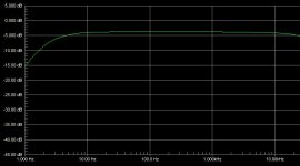
I saw something on your picture that is going to tilt the response somewhat up towards the highs and will surely contribute to a false tonal balance. That capacitor looks smaller than the 16nF asked by the circuit, at a measured 14.31nF. You must do something about that, by adding some small one in parallel.
kstlfido said:Airy! Bit thin on the bass.
-Kent
I saw something on your picture that is going to tilt the response somewhat up towards the highs and will surely contribute to a false tonal balance. That capacitor looks smaller than the 16nF asked by the circuit, at a measured 14.31nF. You must do something about that, by adding some small one in parallel.
Attachments
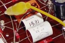
Yes, it has been trimmed. You can barely make it out, but there are two 1n silver mica just behind the yellow alligator clip. Found the lowest pair, totaling 1.93 nf. Total is 16.24 nF; close enough for now. The other multicap (right board) is 16.38 nF. Both these were supposed to be 15 nF- go figure. I'll need to get some of those russsian green ps and make up some proper 16 nF's.
Salas, I've noticed on some of your schematics, this cap is 15.8 nF. Is that correct or is 16 nF?
Lowered the VTA on my TT and helped the bass a bit. Still listening. Got a bit of hum; need to box it up.
Parts came today for the shunt reg. I will hold further comments until that's in. The mosfets I got are SFH9240, they OK?
-Kent
I'll need to get some of those russsian green ps and make up some proper 16 nF's.Salas, I've noticed on some of your schematics, this cap is 15.8 nF. Is that correct or is 16 nF?
Lowered the VTA on my TT and helped the bass a bit. Still listening. Got a bit of hum; need to box it up.
Parts came today for the shunt reg.
I will hold further comments until that's in. The mosfets I got are SFH9240, they OK?-Kent
I am happy that they are actually OK for value. So we can concentrate on proper PSU and hook up. Yes your Mosfets are very nice Fairchild jobs, totally OK. Those 15.8nF etc are trimmed for slight differences in internal circuit impedance between versions. Yours is fine with 47k, 47n, 16n. For that little hum, better attach your coax shield, not using the cable as pseudo balanced, especially for input. If it is so of course. These are practical things, I am sure they can be sorted out. In general this RIAA is not a PITA to make it quiet. You did not tell about the impedance that you drive with the RIAA or what is the TT, cart, amp, speakers. Maybe it is helpful we know.
After you listen with the shunt, I will be happy to know how you listen, what you would like to alter tonally, etc. There are many slight tonal shifts that we can achieve.
After you listen with the shunt, I will be happy to know how you listen, what you would like to alter tonally, etc. There are many slight tonal shifts that we can achieve.
Thanks Salas. I have been adjusting for 8.1v on the drains. Need to let it settle for about 15 min after power on. Heh, just like tubes!
My system is follows-
Im using a Benz Micro Glider ser. 2 LO- ~0.3 mV on a VPI HW19 mkIII with stock arm.
My line stage is an MFA Magus B (1990). 50k input impedance.
In tube parlence, these are 'cathode' biased, right? If so, then there is local degenerative feedback as the cathode, er, source bias resistors are unbypassed. I did put a 1000uF bypass on one board and as expected, the gain increased.
Electrons is electrons! Silicon or vacuum...
kstlfido said:Thanks Salas. I have been adjusting for 8.1v on the drains. Need to let it settle for about 15 min after power on. Heh, just like tubes!
My system is follows-
Im using a Benz Micro Glider ser. 2 LO- ~0.3 mV on a VPI HW19 mkIII with stock arm.
My line stage is an MFA Magus B (1990). 50k input impedance.
In tube parlence, these are 'cathode' biased, right? If so, then there is local degenerative feedback as the cathode, er, source bias resistors are unbypassed. I did put a 1000uF bypass on one board and as expected, the gain increased.
Electrons is electrons! Silicon or vacuum...
Hi Kent,
Yes I am a tube guy too, and I made it with a tube head mind.
You got +6dB with the bypass (shown on my reply#110 schematic too), do you feel like needing it? With your 8mA Idss you hit about 57dB gain without the bypass caps. If they are needed, the bypass cap is audible for quality, just like with tubes... Nice TT and cart by the way, that's the classic VPI I like most. Made like a tank.
Darn, i'm getting confused now. 
I have all the parts now, and was planning to make the 36dB version from post #152, and the shunt from post #142, but suddenly realize that the Riaa is supposed to run from 24V, and the shunt gives 37V.
Is it just a matter of changing the zener in the shunt, or is it a little more complicated, as i fear ?
Best regards
Ebbe
- Home
- Source & Line
- Analogue Source
- Simplistic NJFET RIAA