Looks like you pick it up electrically the 120Hz when I don't. Are those Cardas you run from cart to phono really shielded for such a run? Also is there a separate arm chassis ground wire running to the phono chassis? The RCA in to PCB wiring must be shield to ground both ways too. Do I see one way to RCA on those pics? Its a fine point to be sure I see well.
The cardas shielding is quite good. I have read several people doing it. You hit on somehting I need to check later this afternoon. The arm is grounded as well as the chassis., however, it is not on a seperated wire. I hooked them to the shield which is poor practice. I will rewire the ground this afternoon when I get back.
P.S. I forgot that I did that. It was one of those I'll remember it later things at 12:00am.
P.S. I forgot that I did that. It was one of those I'll remember it later things at 12:00am.
Last edited:
The cardas wire is like a 4 conductor with RG shield. The four wires are "specially braided" 33awg wire. It is wrapped in PTFE and then a braided shield. The shield is quite dense and approaches 100% coverage as my eyes see it.
Internal to the head amp, the signal in is shielded two conductor with the shield terminated to the pc board. There is a section, about 8cm, of the external wire that is unshielded where it splits into left and right. I could shorten that up, or try to figure out the best way to shield.
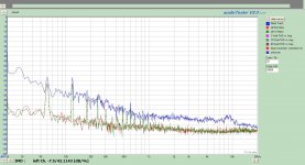
I did redo the ground and now have a seperate wire to the head amp. Attached is the measurements. I also through in the 300Hz +12dB to make the graph busier.;-). Big improvement but not solved. I will remove the motor ground and attach it to mains ground on the TT. I will also instal yin/yang diode to decouple any potential ground loops and report back later.
Internal to the head amp, the signal in is shielded two conductor with the shield terminated to the pc board. There is a section, about 8cm, of the external wire that is unshielded where it splits into left and right. I could shorten that up, or try to figure out the best way to shield.
I did redo the ground and now have a seperate wire to the head amp. Attached is the measurements. I also through in the 300Hz +12dB to make the graph busier.;-). Big improvement but not solved. I will remove the motor ground and attach it to mains ground on the TT. I will also instal yin/yang diode to decouple any potential ground loops and report back later.
Attachments
We may be talking past each other here. The shield for the signal wire is only a shield. All signal is run on the four conductors R+, R-, L+, L- run internal to the shield. I will agree that the shield needed to be seperate from the arm/chassis.
Need to work the last bit out.
With this turntable, there is no metal chasis, so the motor, bearing, and arm are electricaly seperate. I found no difference If I attached the bearing and mototr direct to mains ground or to the head amp chassis.
I have not yet installed the ying/yang diodes.
Need to work the last bit out.
With this turntable, there is no metal chasis, so the motor, bearing, and arm are electricaly seperate. I found no difference If I attached the bearing and mototr direct to mains ground or to the head amp chassis.
I have not yet installed the ying/yang diodes.
With your last graphs I have no worry that your phono may isn't in decent spec working condition. I see that your last test vinyl runs approach all normal trends I have seen. I use single core and shield internal signal wire BTW.
I could get lower noise floor FFT (especially by not levelling out towards the highs) but I can not assess the contribution of the card, computer's psu, or how the software interacts in another FFT system. Is there a ground lift button you can compare in/out?
I could get lower noise floor FFT (especially by not levelling out towards the highs) but I can not assess the contribution of the card, computer's psu, or how the software interacts in another FFT system. Is there a ground lift button you can compare in/out?
I am using pmillets sound card interface. I float the inputs as grounding them sends the harmonics through the roof. The computer is a laptop, I should try it on battery next time.
I wonder how muc of this is related to the torroid. I have the r core coming in a week or so. The proper riaa and interstage caps will also arrive by then.
I unfortunatley did not have any decent .1uF caps to replace the Wima like I had intended, I do have .2uF Mundorfs but not sure of what affects it may have on the riaa.
I am building a measurment PC using an MAudio 192 Card.
Don't use 0.2uF because I have based the VLF FR on the 0.1uF to 1Meg thing, it will kick Riaa also a bit in the lows. Best there, is either the $$$ Jupiter wax for some excitement but good one, or Teflon. FT-2/3 does very well, a transparent gent. Its not a top American Teflon cap, there is more ''light'' in them TRTs and Vcaps but their prices DONT help, neither they are heads and shoulders above the USSR NOS guy IMHO.
Those last non shielded lengths to RCA in, can play a role, the toroid surely has a bad role confirmed reputation in single box phono, plus the nearby AC inlet, but your double enclosed box may don't give a damn about bad reputation, you will see if there is any change when you will fit the horse races shaped guy. It usually lends a better tone anyway.
Those last non shielded lengths to RCA in, can play a role, the toroid surely has a bad role confirmed reputation in single box phono, plus the nearby AC inlet, but your double enclosed box may don't give a damn about bad reputation, you will see if there is any change when you will fit the horse races shaped guy. It usually lends a better tone anyway.
measure your CDP output.
Done, and damn you're right the signal is around the signal output of the 66dB version from the phono - that makes all easier because I thought the 2Vac from a CDP is the average.
Sorry all for my miscarriage
")
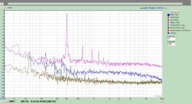
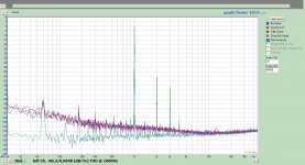
Working through my measurement system and the Simplistic trying to work out the 60Hz harmonics. I think I have resolved it. First of all I ran the laptop on battery, the result was clear, that was the majority of the problem. Secondly I then looked at the direct loop spectrum and compared it to the spectrum obained passing through the simplistic. I know that using the USB cable to power the pmillet interface does pick up a small amount of 60Hz. The FFT overlay shows this clearly. The 60Hz and associated harmonics in the attached graph are the result of the measurment system.
Even with the 60Hz, disconnecting the laptop from the charger makes the system useful.
In the attached plot 0dB corresponds to a .30mV input signal to the simplistic.
Aqua : Soundcard interface direct loop
Blue : 1kHz Signal .30mV signal though the simplistc
Green: Box fully closed 1kHz .30mV through simplistic
Red : 0.0mV signal through simplistic.
Now to repeat this with the TT hooked up.
Attachments
- Home
- Source & Line
- Analogue Source
- Simplistic NJFET RIAA