Well it appears on the surface that we had a succesful several nights. After finding a bad solder joint and a wrongly jumped temporary RIAA cap, the headamp actually amplified a signal. Several in fact.
Several measurements are shown attached.
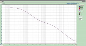
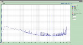
L/R Channel Frequency response.
Grounded input (actually 50R terminator)
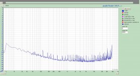
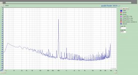
500, 1000, 5000 FFT.
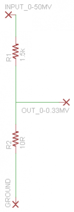
I have alot of noise in the cable voltage divider that I built, however, I don't think it is all of it. It is 1:151 using a 10R:1.5k precision resistors. The divider is shielded inside the RCA housing. Signal fed into the head amp was .3mV. Most of the grass is related to my test gear and the environment I am testing in. Will have to move it out of the area and away from all of the computers and hardware.
What is nice is that the 60,120,etc spikes are almost non-existant. So no HUM!!!!!. Also the Left and Right traces almost fall on top of each other. Blue being right and Red being left.
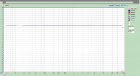
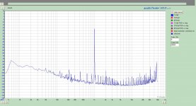
I also attached the corrected straight through test of the corretion file. A little minor tweeking left to do but it isn't bad. My eyes are crossed at this point so time for bed.
Several measurements are shown attached.
L/R Channel Frequency response.
Grounded input (actually 50R terminator)
500, 1000, 5000 FFT.
I have alot of noise in the cable voltage divider that I built, however, I don't think it is all of it. It is 1:151 using a 10R:1.5k precision resistors. The divider is shielded inside the RCA housing. Signal fed into the head amp was .3mV. Most of the grass is related to my test gear and the environment I am testing in. Will have to move it out of the area and away from all of the computers and hardware.
What is nice is that the 60,120,etc spikes are almost non-existant. So no HUM!!!!!. Also the Left and Right traces almost fall on top of each other. Blue being right and Red being left.
I also attached the corrected straight through test of the corretion file. A little minor tweeking left to do but it isn't bad. My eyes are crossed at this point so time for bed.
Attachments
If that grass isn't inherent to the phono build and its in the set up, then its perfect. Go 48kHz/24bit, 65536 points. Divider should be 1.5k series to 15R shunt. Yes no fundamental hum bands. But we can't be sure what can be masked. For circa your gain with single Jfet input can show like that. The 16k spike is from my neighbor's CRT TV.")
Attachments
Hum.... So you can compare... let us know the differences
Does the Borberly I/V perform bessel filtering after the dac ?
What dac are you using ?
I bought 3 boxes at Hifi2000: 1 for Salas NJFET RIAA & 2 for DAC so now I have a lot of work, but when I can I will tell the you the subjective differences between both regs.
The Borbely I/V use 3rd order Bessel filter but can be configured of several ways: for example now I'm using passive I/V with resistor instead active with better success.
Buffalo II from Twisted Pear guys.
I will work on my set-up tonight. If you remember I had the same issue when working with my OPUS amp. I have to pull my notes to see what I did to get a clean measurement.
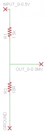
Attached is the schema of my voltage divider. It appears right to me and behaived appropriatley.
Attached is the schema of my voltage divider. It appears right to me and behaived appropriatley.
Attachments
Looks OK as a divider. Its how I wire mine too, and I have even grabbed no mains hum off the noise bed in some double box build, so it can't be the divider.
But your 2ndH looks around -90dB which correlates with mine (if I run it -20dB signal), but I don't know the calibration, what mV RMS is your -20dB signal? Can you calculate gain @ 1kHz? That would be another good sign about working properly if near target. Channel tracking I see very good without trimming any resistors, and Riaa flat curve good. But not spanning 40dB on the other, the curvy plot. Are those Riaa caps 47n,15n meausured n' matched?
P.S. Did you write a correction file against textbook Riaa and included the card's kinks, so to produce the flat?
the output from your fixed attenuator is 10/1510 =0.0066 times the input.
500mV input gives 3.31mV output, but only if the receiver impedance is near infinity.
For reasonable accuracy, the receiver Rin>>10 times 10r. Try 1k0 which will give an apparent output reading of 3.28mV.
The error is <1%
500mV input gives 3.31mV output, but only if the receiver impedance is near infinity.
For reasonable accuracy, the receiver Rin>>10 times 10r. Try 1k0 which will give an apparent output reading of 3.28mV.
The error is <1%
if the receiver has Rin>>10*10r then the error is quite small.
One can calculate the error and make allowance for it if the source resistance and receiver resistance are known.
Note, the schematic shows the output as 300uV, not 3.31mV
At 45mV to the attenuator probably. He noted 0-0.5V input, so he likely refers to his target output matching the cart's nominal and his input range to the divider spanned by the audio card.
Andrew you caught an error in my schematic of the divider. It should read 0-50mV. In my haste this morning I typed in the wrong value. Attached is the corrected schematic, please forgive my error.
Salas, The corrected response that I plotted is only correcting the output of the soundcard interface with the low impedance it is driving. Basically I established the corrdection by measuring the output of the card for each frequency while hooked up to the divider. I have no RIAA correction in the measurement system as of yet. So the FFT's shown are uncorrected for RIAA. As such the higher frequencys are down in dBfs proportional to the filter response.
The riaa caps are matched, however the 15nF cap is running 15.6nF with the limited sample I had to use. The 47nF is 47.1nF and the R is spot on. I bought these more for proof of concept since they were cheap and had quick delivery. The better caps are coming but will be another week or so untill they arrive. I figured I would trouble shoot and make sure both channels respond the same with what I had and then fine tune the RIAA curve with the correct caps later.
I will try to measure gain tonight if I have time. I am a little bit confused on what benchmark to use. Should I compensate for the RIAA, i.e. add back the dB lost due to the filter or should I calculate it based on actual response at 1000Hz? Obviously the latter would result in lower gain.
The FFT's taken last night were at 0.3mV input. 45mV on the sound card output.
edit> When I set the scale in the correction file 0dBs is 0.3mV input. Or 45mV output from the card. I measured that on my oscil scope.
Attachments
Last edited:
You did very well you gave it a massage and looked for gremlins. As it is then I see some blind spots in the measurement set up for noise, your now caps values should overshoot Riaa in the highs and not left behind as it now shows, in other words I see hints that maybe its perfect in trends but not proof due to insecurity in gear. At 1kHz Riaa is 0dB, so if you feed 0.3mV 1kHz and measure with your DVM AC mV OUT, you can divide and log20. If that result is encouraging too, hook it up on the TT and listen if its clean and silent because with that noise floor in the measuring loop we can't say 100%. If it will be full OK just a bit soft for tone is you overshoot 15n.
Its within experimental error even. Very well. Hook it up then to know if its really silent enough in the actual system first of all. If it is silent and feels generally right, then you can debug the measurement setup's noise floor in leisure and recheck. I wonder if you just loop your card on its own, is there high spikes floor? I wanna assure its not the output buffer of the phono needing some series damping resistor and oscillates without.
The headamp is pretty quite. I have to go to full volume to hear a faint hum. I think that we need to install a series damper resistor however as the noise floor in a direct loop is much lower. The grass is also greatly reduced but not eliminated. With the head amp it seems to be very cable dependent.
I have to rewire the turntable before I can play an album. (Which I am doing now). The head amp will pick up hum if I lay an input cable on the mains cable so it is amplifying. I would like to listen to the test lp and see if it is clear before I put it back on the bench for further work.
I have to rewire the turntable before I can play an album. (Which I am doing now). The head amp will pick up hum if I lay an input cable on the mains cable so it is amplifying. I would like to listen to the test lp and see if it is clear before I put it back on the bench for further work.
The difference on the other hand between a line level card loop and a 57.5dB gain loop is substantial for getting it looking higher spiky for that... hmm no real hum when in the stereo system you said... And there is extra gain in the preamp... Is the phono without a top also, open? I would have expected a strong enough roar in full vol pot from hum frequencies to treble if it was actually oscillating. If you confirm there will be any untoward noise floor on the speakers with the actual TT hooked up, we can use a 33-100R output damper, but I would like to avoid it because it will hold back dynamics a bit if not strictly necessary in your system. But you can try it out just for measurements in the start, and see if it changes something. I did not have it oscillating without a damper in 2 phono in two different systems up to now, that is a why I am reluctant and trying to avoid if possible.
Hum is only present at full volume. No roar or indication of oscillation. The headamp is closed up with both steel cover and aluminum cover on.
I will have the wiring of the tonearm completed tomorrow hopefully. My eyes are getting older and the wire exceedingly small even with 1.5x glasses that it is taking me a bit at this time of day.
I will report back when it plays the test LP.
I will have the wiring of the tonearm completed tomorrow hopefully. My eyes are getting older and the wire exceedingly small even with 1.5x glasses that it is taking me a bit at this time of day.
I will report back when it plays the test LP.
When about ready preparing, level the TT well first. If your test disc has tracks for setting the anti skating, be thorough. Its the most critical part IMHO and never can be set right with dents and predetermined scale. Vertical tracking force & rake angle are easy to weigh and see.
- Home
- Source & Line
- Analogue Source
- Simplistic NJFET RIAA