


power line gremlins
Hello,
This is a huge thread; I have been looking in over the years.
I get the sense that there is a flood of current through a shunt regulator and the P2P variation of the load is small compared to the current through the shunt. The disturbance caused by the load P2P is relatively small. The shunt regulator’s active devices have relatively less work to do compared to a Maita regulator where all the current passes through the load.
I have searched this thread looking for FFT’s and only found a couple of references but no plots. Looking at all the photos of shunt regulators many / most sit open on the bench top. From my experiments and FFT’s line frequency and related harmonics get into everything and show up in the FFT’s.
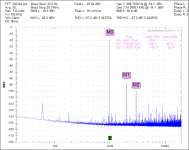
Most recently I am playing with a Class A 12B4A headphone amplifier that idles at 0.035A with a shunt of 0.025A for a total of 60ma. There is a struggle with 60Hz line frequency, 120Hz rectifier hum and their higher frequency relations. I have placed the HV transformer, Rectifier Bridge and CLCRC pre-filter into a grounded steel box. Much of the power line stuff is reduced. 180Hz is near -135dBV, 120Hz is at -140dBV. The 60Hz remains untouched. Even with the HV switched off the 60Hz and 180HZ remain. The next power line attenuation target is the heater power supply.
Is anyone else testing and chasing these powerline gremlins?
Please share your adventures!
Thanks
DT
Hello,
This is a huge thread; I have been looking in over the years.
I get the sense that there is a flood of current through a shunt regulator and the P2P variation of the load is small compared to the current through the shunt. The disturbance caused by the load P2P is relatively small. The shunt regulator’s active devices have relatively less work to do compared to a Maita regulator where all the current passes through the load.
I have searched this thread looking for FFT’s and only found a couple of references but no plots. Looking at all the photos of shunt regulators many / most sit open on the bench top. From my experiments and FFT’s line frequency and related harmonics get into everything and show up in the FFT’s.
Most recently I am playing with a Class A 12B4A headphone amplifier that idles at 0.035A with a shunt of 0.025A for a total of 60ma. There is a struggle with 60Hz line frequency, 120Hz rectifier hum and their higher frequency relations. I have placed the HV transformer, Rectifier Bridge and CLCRC pre-filter into a grounded steel box. Much of the power line stuff is reduced. 180Hz is near -135dBV, 120Hz is at -140dBV. The 60Hz remains untouched. Even with the HV switched off the 60Hz and 180HZ remain. The next power line attenuation target is the heater power supply.
Is anyone else testing and chasing these powerline gremlins?
Please share your adventures!
Thanks
DT
Attachments
That's a really good harmonic noise result already I would think for a tube build considering its unavoidable extensive wiring, its big various components, the glass encased big metal elements exposed to probable fields, plus their wide area heaters circuit. Almost all of it at -135dB or under and the mains frequency at -120dB its no mean feat. Maybe by adding grounded shield caps on the tubes and by paying best attention to heaters PSU and its loop area can do little better. Heaters are already on DC with return side referenced to chassis I presume.
Attachments
More experiments to follow
Hello,
The temporary heater power supply is a Sorensen 0-15VDC variable bench tool. The temp heater supply is referenced to ¼ the raw high voltage supply (~+42VDC to the cathode) by a voltage divider.
I am looking at a LT3080 for the heater regulator. I am a bit concerned about the well filtered and regulated high voltage supply and the less well filtered heater power supply commingling at the voltage divider. More experiments to follow.
Any other thoughts or ideas?
DT
Any other thoughts or ideas? How and at what voltage is the heater supply referenced to the HV supply . at 45 volts above the ground most tube heater supplies are the most quiet. . I.E. 12 volt supply elevated 45 volts above ground . Thus biasing the heater to cathode capacitance..
Thanks Triodetom,
There is a 300K + 100K voltage divider placed across the pre-filtered high voltage supply ~240VDC, placing the heater reference at ~60VDC above ground. The 12B4A cathode is 17.5VDC above ground. The heater reference ends up ~42VDC positive relative to the 12B4A cathode.
@ All,
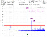
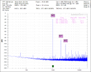
For grins I placed the shunt regulator, amplifier and the QA401 audio analyzer all in a grounded steel junction box. The idea came from Salas' suggestion to shield the tube(S). The mains 60Hz FFT spike is improved by ~10dBV
DT
There is a 300K + 100K voltage divider placed across the pre-filtered high voltage supply ~240VDC, placing the heater reference at ~60VDC above ground. The 12B4A cathode is 17.5VDC above ground. The heater reference ends up ~42VDC positive relative to the 12B4A cathode.
@ All,
For grins I placed the shunt regulator, amplifier and the QA401 audio analyzer all in a grounded steel junction box. The idea came from Salas' suggestion to shield the tube(S). The mains 60Hz FFT spike is improved by ~10dBV
DT
Attachments

Thanks for ....... for your High Voltage Shunt Regulator.
Hello Salas,
Thanks for all the DIY community support and for your High Voltage Shunt Regulator.
Hello All,
Not wanting to be chased away for being OT I will save the discussion about the QA401 analyzer for tomorrow morning in my 12B4A headphone thread.
I will come back and share the final version of coordinating the heater supply with the High Voltage Shunt.
DT
- Home
- Amplifiers
- Power Supplies
- Simplistic MosFET HV Shunt Regs