No change with RC? Then its no problem due to a weird effect like oscillation. On the other hand if with increasing CCS the voltage goes up and up it means the tube circuit asks more and more current and the CCS current limits it (protects it) each time. Points to wrong loading.
I'ts well connected, pin 1 to plate, pin 3 not connected, pin 5 B+, pin 7 output, pin 9 output gnd.
Do you want I load the output with a resistor of 600 ohms?
An externally hosted image should be here but it was not working when we last tested it.
Do you want I load the output with a resistor of 600 ohms?
Felipe, this is the DC game, transformer secondary loading does not play. ")
Before you change anode resistor with transformer, you must measure anode voltage and anode current, this is the target operating point.
If you change resistor to transformer, the target op. point must remain the same.
The "new" B+ voltage is the op. point -anode- voltage + Ia*DCR of primary.
Before you change anode resistor with transformer, you must measure anode voltage and anode current, this is the target operating point.
If you change resistor to transformer, the target op. point must remain the same.
The "new" B+ voltage is the op. point -anode- voltage + Ia*DCR of primary.
Do you want I load the output with a resistor of 600 ohms?
Its good to have it only for AC reasons like in case noise or other signal goes in during the tests.
Secondary loaded with 600 ohms resistors still can't regulate SSHV2 Vout.
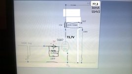
In place of OPT connected 10K anode load resistor and B+ 210.6V, voltage at plate is 69.7V one triode the other 72.6V, voltage across resistor 141.2V & 138.3V
Can't change B+ with the SSHV2 trimmer, I suspect bias is fixed due to the -3.3V battery connected to grid?
In place of OPT connected 10K anode load resistor and B+ 210.6V, voltage at plate is 69.7V one triode the other 72.6V, voltage across resistor 141.2V & 138.3V
Can't change B+ with the SSHV2 trimmer, I suspect bias is fixed due to the -3.3V battery connected to grid?
210-70=140V plate resistor drop. 140V/10K=14mA. Since it works with the dummy set 70V and 50mA. If all is analogous and the CCS current is enough it should stay at 70V with the preamp connected. I don't know what system interaction goes on there but when it works normally with a dummy its not damaged at least. Put 10 Ohm between the reg and the primary to measure the drop and find the current that the preamp with OPT draws. Bring out the scope and look for oscillations if the current is normal as it was with the 10K anode load. Three things it can only do wrong is either current limiting or oscillating or burning.
P.S. With the 68K Ref resistors you are at the bottom low of the adjust range now says the spec. Try 2X24K 1W for below 100V easier range of setting.
P.S. With the 68K Ref resistors you are at the bottom low of the adjust range now says the spec. Try 2X24K 1W for below 100V easier range of setting.
Vgs should be 1.5V to 2V on both DMOS. When having enough Vin minus Vout difference (few volts minimum) and the DMOS are healthy its the same Vgs result in LV CCS testing also. Minimum trimmer that gives max current of DMOS capability always tends to zero no matter if its 500R or 200R max.
- Home
- Amplifiers
- Power Supplies
- Simplistic MosFET HV Shunt Regs