
Which one?
It was the 1.8k resistor in the emitter leg of Q4. It was too low - 100 ohms.
Several thoughts...
I was pointed to the thread by a person with whom we discussed some other topic. I read all the pages with great interest and was tempted to answer several posts from the ancient several years ago while reading. I also have built several high voltage shunt power supplies, mainly different schematic and layout, so the topic is rather familiar to me and interesting too.
I'd like to point several concerns raised in the previous messages about reliability, usability, capability and other. Please do not take my message as some kind of critics, English is not my mother tongue and phrases could be rather straight and tedious.
The main difference between the SSHV1 and 2 is the CCSs' layouts. They are both (main and Vref) now 2-point circuits. This fact gives us great flexibility in usage. For example, we can easily convert the "positive" regulator to "negative" just by connecting the main CCS (without any changes!) to negative PSU rail. The input would be R5, the output - drain of Q1. The "conversion" is useful in many ways: balanced power supplies (with the possibility to use xxxV-0-xxxV transformers), extending the output voltage range up to 800V (two symmetrical SSHVs), sharing current capabilities (and heating too) between the "halves" (the same method), "isolation" from the transformer in both plus and minus rails and so on. Even if the SSHV2 is used as "standalone" device the possibility to move the main CCS to the ground circuit has (for some builds and circuits) several advantages too (the drain of the DMOS would be just at difference voltage potential to the ground, for example - can be less dangerous to use metal case for heatsinking). Another consideration - the current limit, which could be easily lifted by connection the main CCSs blocks in parallel. I'd consider also some different 2-port CCS circuits as possible substitutes (for example, low dropout 3-point linear regulators strapped as CCS with cascoded MOSFET on top). What is the lengthy text about? I think in the SSHV 2.1 version we can have means of change the position of the main CCS (by jumpers, for example). It gives also the "slice point" for step-by-step checking of the device (first - CCS, second - shunt). I also think that the SSHV3 could be modular in design (main CCS, sensing circuit, shunting circuit...) - that way the usage can be virtually limitless.
The same consideration about possible substitutes can be thought for Vref CCS too.
The second part of improvements - the sense amplifier circuit. It was made as cascode which is a great idea in my opinion. But I'd be consistent in the improvements. Addition of only one JFET (together with one resistor) instead of R8 (form CCS-load for the cascode) will linearize the whole circuit and boost its open-loop gain. It can help to eliminate (very small) influence of the sense amplifier to the total current consumption too (it will have fully determined current from the input (sense) side and the output (control) side).
The third part of improvements - the shunt itself. While I understand that most DIYers are happy with current part (Q3=IRF840) it is feasible to ease the part choice. I think about cascode implementation too. That way it could be used in two different configurations:
- true cascode: the bottom transistor is chosen by low input capacitance for best frequency response, the upper - for necessary power characteristics;
- sharing: the top and bottom transistors are identical and shares the power stress between them.
This modification can be easily implemented in the SSHV2.1 design - just jumper to eliminate or enable the second (top) MOSFET. As soon as the MOSFET does not draw any current from the gate side the "bias" for the top MOSFET gate could be gathered from Zobel network's capacitor (divided by two to form the "middle point").
The last thought... The SSHV deals with high voltage. The concerns about good isolation of the heat sinks were raised several times. Unfortunately, the tabs on the power MOSFETs in the current configuration are at high voltages. I prefer to modify the schematic in the way the bare metal part of the power transistors be near the ground potential as much as possible. I understand that it means huge rethinking, but I believe in the future while modifying the circuit we should take into account the problem too.
Thanks for the thoughts on this concept. Modularity, reversing, totem pole build up, active loading, paralleling, further cascoding etc.
There is the concept and there are the P2P & PCB examples in this thread.
In SSHV the first "S" stands for "simplistic" as we all know, so the SSHV2 is made for low parts count and a certain bracket of popular applications.
The spec its not too pushed for staying on the safe side for general compatibility.
It was studied to strike a balance both in objective and subjective scale though. Had an independent builders pre run for that purpose also.
Active loading in the cascode error amp ups the gain but loses the flatness for a 4 fold contrast between the audio spectrum Zo extremes for instance, creating a subjective "pinch".
It would take more circuitry to bring it all back, but in lower Z. Output cascoding, or drive buffering, etc. Then the phase becomes more demanding for pre-determined loads and terminations.
When 10 mOhm to 1mOhm centre spec is easy to lose in a practical application due to a joint for instance, questionable for tube circuits demands also, simplicity was chosen.
All in all, everything you mention is well applicable in special purpose spin offs from this general concept, but for me to advance in some well practical SSHV3 issuing in the future it would take a concrete practical concept first. Modular and/or reversing it would target advanced builders only nonetheless. But its a way.
Yes, I saw this answer several times through the thread, but the schematic itself became stable around 2 years ago already and maybe there is time to look for improvements in the safety field also.The spec its not too pushed for staying on the safe side for general compatibility.
Sorry for my poor understanding... Could you rephrase this into simpler English?Active loading in the cascode error amp ups the gain but loses the flatness for a 4 fold contrast between the audio spectrum Zo extremes for instance, creating a subjective "pinch".
Can't understand the phrase too. The values you are mentioned are fully dynamic, any static resistance doesn't have any relation to them (if I correctly understand the context of the word "joint"). If you mean the connection between a regulator and a circuit - yes, it makes sense, but not with remote sense I think. Secondly - I suggested the cascode not for improving Zo (it is not the only characteristic of regulators), but for widening the good circuit usage in many ways without severe testing and risk.When 10 mOhm to 1mOhm centre spec is easy to lose in a practical application due to a joint for instance
But... I wrote about very simple mod too (about main CCS positioning) - it does not change the circuit at all and brings new usages easily.
-"If it ain't broken don't fix it" is a wise American saying. There could be drop in suitable plastic encapsulated power parts to look for though.
-Substituting R8 by a CCS has been tried and creates a dip in the output impedance, detected as a pinched sound. It can be brought down altogether flatter but it takes additional complexity.
-There are unknown wires, tracks, connections, further on from the feed 'nodes' in the random audio circuits it serves.
-There is no big demand for heavy current applications reg by tubes users for as much I have seen in this thread, SSHV1 could do much more but seen seldom use for >100mA. Still more current, output sharing, reversibility etc. are attributes that I would consider for a boosted SSHVX version in the future. Yet, I expect the majority of the users leaning on the less parts to go wrong, cheaper, smaller SSHV2. Its better offering a gamut of suitability than stopping something declaring it obsolete when it has a useful application field.
-"If it ain't broken don't fix it"
"Only those who keep going arrive at the target" (Russian saying, liberal translation)DIY is fun, but not sitting at the same place "to rest on one's laurels".
OK, possible. But the parts usually have much lower power and temperature characteristics.There could be drop in suitable plastic encapsulated power parts to look for though.
Could I have a look at this (thread? forum? results? - anything)? Seems strange for me.-Substituting R8 by a CCS has been tried and creates a dip in the output impedance, detected as a pinched sound. It can be brought down altogether flatter but it takes additional complexity.
Ok, but it could be just the other side of your opposition to, for example, using the device in power amps. I don't even say about using CCS itself in other designs (in case of modular way of going).-There is no big demand for heavy current applications reg by tubes users for as much I have seen in this thread, SSHV1 could do much more but seen seldom use for >100mA.
I'm not against the current design and layout and said, for example, that with the cost of adding 2 jumpers the SSHV2 could be used in more designs and situations. No additional parts, no flaws in simplicity. Minimum changes in the PCB and you can add testpoints for step by step debugging of the setup.
Cheaper? More size? I can't say so taking into account demanding heatsinks in actual design, power resistors, usual routine of "changing all semis", problems of isolation the big metal chunks and so on.
Dear Salas,
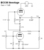
I am about to wire up this ECC88 linestage, and will try your HV Shunt. However, I am a little confused which HV Shunt version to use. Could you take a look at the linestage schematic and advise?
PS: My power transformer has a center-tap output of 370V-0-370V, and I am planning to use 5U4G tube rectifier.
Thanks.
Attachments
SSHV2. Use some RC before it in case you got more than 50V input to output drop to spare. 20V drop over the regulator will be plenty.
Thanks, Salas. I will try this SSHV2.
Last edited:
SSHV2. Use some RC
An LC would be ideal since there is so much voltage to spare. 370 minus 30-40 V drop times 0,9 is about 300 V and the SSHV has plenty to spare for the circuit
An LC would be ideal since there is so much voltage to spare. 370 minus 30-40 V drop times 0,9 is about 300 V and the SSHV has plenty to spare for the circuit
Yes, Stajo. That should be no problem with me. The only problem I just found is I cannot find some of the components here in Vietnam including DN2540, KSA1381, and SK117. Not sure if there are substitutes available.
If you can order from for example Mouser they have DN2540 and KSA1381. SK117 I would suggest Ebay
Yes, I think I can. Thanks, Stajo.
Thanks for the quick answer.I checked,the CCS can give up to somewhat a good 3mA to snoop away from the current through the two 68k.The leftover is for the base of Q5,just to get the MosFet start conducting on the wanted outputvoltage.
Not much of a regulation,no reference (the zener is useless),all depend on the Hfe of Q5.It will work but I don't like it.
Mona
Not much of a regulation,no reference (the zener is useless),all depend on the Hfe of Q5.It will work but I don't like it.
Mona
For what's intended, i.e. tube amps/preamps there's no need for a rock stable precision reference voltage. The CCS/resistor "reference" is quite sufficient in this application, and it's the fact that it's less than perfect a reference is not as bad a price to pay for the advantages it offers, which are what one really wants, IMHO. But hey, you can always replace the CCS/resistor reference with your reference of choice: string of zener diodes, VR tubes, etc.
For what's intended, i.e. tube amps/preamps there's no need for a rock stable precision reference voltage. The CCS/resistor "reference" is quite sufficient in this application, and it's the fact that it's less than perfect a reference is not as bad a price to pay for the advantages it offers, which are what one really wants, IMHO. But hey, you can always replace the CCS/resistor reference with your reference of choice: string of zener diodes, VR tubes, etc.
Indeed, and than there will be the penalty of higher noise.
- Home
- Amplifiers
- Power Supplies
- Simplistic MosFET HV Shunt Regs