Hello guys,
take a look on my schematic and my pcb, i truly want your comments and if this will be workable without hum and other problems.
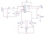
it is an inverting design .. the 56K resistor in the input is there because i dont indent to use a POT
is everything correct so i can continue with construction?
did i miss something?
any comments for the pcb? what can i do to make it better??
thank you very much!
take a look on my schematic and my pcb, i truly want your comments and if this will be workable without hum and other problems.
it is an inverting design .. the 56K resistor in the input is there because i dont indent to use a POT
is everything correct so i can continue with construction?
did i miss something?
any comments for the pcb? what can i do to make it better??
thank you very much!
Attachments
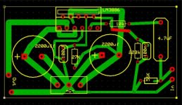
KostasTheGreat said:power lines are thicker now... better?
what about the schematic? is it correct? im more worried about this
Power lines should be thicker and distance to caps shorter.
1) Do a quarter turn on the left 2200uF cap, so terminal is up and closer to -V pin. Go as close as you can.
2) Move the right 2200uF cap to the left side, above the other cap. Terminal will be then closer to +V pin, just a cm or so. As it is now it's a bit far from pin.
3) Solder the muting 27K resistor on the copper side, right over pins and add a bypass capacitor, as datasheet recommends. This bypass is not critical and cap can be far from pin.
4) Add an output resistor closer to "out" pin and also make this track thicker. You can leave the first cm as it is now, to clear from other pins, and make it thicker with copper wire soldered on track. After clearing pins do a wider track.
Carlos
KostasTheGreat said:i separate the power input so it is not so compicated the pcb....
take a look of this now... better? worst??
what resistor should i put on the output of the amp??
The pcb now looks better. Try to design shorter paths for the feedback resistors.
You can use something from 0.1 to .47, 3W to 5W resistor at the output.
Carlos
KostasTheGreat said:0.1ohm 5 watt... the one side to output the other to ground?
thank you for your help..
i will update the pcb and post it again later
No, in series with output. Just cut the output track in the middle and add the two pads.
Carlos
KostasTheGreat said:The feedback resistor will be between the pins
is there anything else i can do or should i start the construction??
Perhaps placing the 10K input resistor closer to its pin, changing its position to just below the pins, horizontally, and placing the 4.7uF cap also horizontally. Hope you get what I mean.
The general idea is to shorten all feedback and bypass tracks, as was the policy on the original Gaincard.
Carlos
KostasTheGreat said:ok .. tell me your comments now")
Looks quite good. Go ahead and make the board.
Carlos
- Status
- This old topic is closed. If you want to reopen this topic, contact a moderator using the "Report Post" button.
- Home
- Amplifiers
- Chip Amps
- Simplified LM3886 amp with PCB