samsagaz said:someone have an one side pcb for lm4870, lm3886 or lm3875?
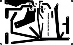
The one above is an LM3886 one side pcb design.
Except for the LM4780, which is more tricky, you can adapt any double side pcb design for 3886 and 3875 and converti into single side. Parts are just a few.
Follow what Kostas changed since his first design to see how it's done.
Carlos
samsagaz said:someone have an one side pcb for lm4870, lm3886 or lm3875?
Check those: http://www.diyaudio.com/forums/sear...d=744366&sortby=lastpost&sortorder=descending
samsagaz said:cjd
have u the schematic for that pcb?
It's all in the datasheet...
") ROut is optional (useful if you try to parallel these).
ROut is optional (useful if you try to parallel these). C
barroccio said:thanks for you all for the pcbs
now i'm lokking at a 3886 pcb like that CJD posted in post 22
The post 22 pcb is for 3875. Try Kostas design for 3886.
Carlos
Parts List:
Resistors:
2 x 220K 1% film resistor
1 x 56K 1% film resistor
1 x 10K
1 x 27K 1% film resistor
Caps:
1 x 47uF
3 x 100nF
1 x 100uF electrolytic
2 x 1000uF 50V electrolytic
1 x LM3886T of course
you can take a look on the schematic
the two bypass caps of the 1000uf will go as near as possible either under the pcb or in the left space beside caps.
search the complete post for the last pcb revision6
Attachments
demogorgon said:uhh.. why the 220kohms resistor from the input to the -V rail?
Look again. 220K resistor is between - input and output. There's another 220K from + input to ground. In fact I'd use a smaller resistor (10K to 22k) there and cut the cap.
Carlos
I think you should look again at his pcb rev.6 as it at least to me is quite clear that he put the 220k resistor between the input and the -V rail.
i didn't think about this before actually realizing that the membrane on my speakers were trying to leave the box! it sets the output at 25V you know...
i put the resistor at the output instead, and it works now, but it diden't before.
i didn't think about this before actually realizing that the membrane on my speakers were trying to leave the box! it sets the output at 25V you know...
i put the resistor at the output instead, and it works now, but it diden't before.
- Status
- This old topic is closed. If you want to reopen this topic, contact a moderator using the "Report Post" button.
- Home
- Amplifiers
- Chip Amps
- Simplified LM3886 amp with PCB