Hi dadod
First click on the picture should open it as a complete schematic view (also with borders included) inside a window of the browser. If you click on the left lower corner where arrow cross is, than it opens in a actual large size. At least that's how it is on my PC.
Yes exactly, but after first click the picture is to small(not everything readable), and after second click on the left corner is to big.
@ dadod,
Kind regards
And how many users here have 1600x1200 screen res.??
And how many users here have 1600x1200 screen res.??
Hi dadod
Here is PrtSc (Print Screen) picture after click one. Screen resolution 1400x1050, Acer Notebook.
Attachments
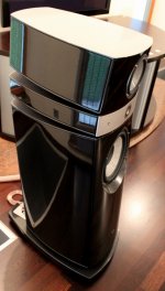
What speakers You drive with it or You maybe use a multi amp arrangement ?
For these speakers it is possible to use only stereo amp (one pair of binding posts per speaker only), for the other speakers I will need 4 amps per channel.
Attachments
Hi Salas
Very nice to see your test bench with new SSA channel running. It is pretty wild one I know, like a mustang, but after setting all parameters it will be like a puppy.
In a case to adjust also the other current source you could easily trimmed DC offset to zero or below. Complete DC nulling can be done with input zero calibration as I already explained. But there won't be any DC offset runaway whatsoever, no worries.
I wish you very nice listening test after mirroring the first channel.
Regards, Andrej
Very nice to see your test bench with new SSA channel running. It is pretty wild one I know, like a mustang, but after setting all parameters it will be like a puppy.
It can be fixed at about +10 to +25mV by varying I2's 100R trimmer a bit. With sine signal it shows -25mV steady DCout.
In a case to adjust also the other current source you could easily trimmed DC offset to zero or below. Complete DC nulling can be done with input zero calibration as I already explained. But there won't be any DC offset runaway whatsoever, no worries.
I wish you very nice listening test after mirroring the first channel.
Regards, Andrej
Thanks for wishes & comments. Considering how it could go before, this one is very workable. Best setting method is on signal source active I saw. When it runs AC its freezing and can go even lower offset. Maybe thermal cross averages by signal heating. Valuable asset is its driver stage CCS that skips cascode loads balancing need for each build and Latfets pair. Runaways around the driver BJTs were often before, even with LED if not watching. Trimmer between drivers sets any output stage Iq in a controlled manner when CCSed. Had used the input nulling on the other side, its installed there, will see how better could go and if to stay when modding the other side. It drops the input impedance further though.
In my SSA amp there was never an issue about DC offset, really never, it was dancing around zero +/-10 mV, maybe just because I matched hFE's totally and thermally coupled the input pair transistors. The only issue was output bias current but that was also OK after working thermall conditions re-biasing.
P.S. What about adding small emitter resistors to Q5, Q6, let say 10 ohm. These transistors can also cause unsymmetry because of their hFE and thermall differences.
P.S. What about adding small emitter resistors to Q5, Q6, let say 10 ohm. These transistors can also cause unsymmetry because of their hFE and thermall differences.
Last edited:
In my friend's build they are coupled, so they were in Ruwe's and it was war zone still. Maybe BC transistors helped you better. You had it BigBT right from the start, right? If yes those are different CCTs.
P.S. Emitter resistors on drivers used to be in my friend's. 22R. To no avail. Since the drivers CCS idea, battle around output Iq stopped.
P.S. Emitter resistors on drivers used to be in my friend's. 22R. To no avail. Since the drivers CCS idea, battle around output Iq stopped.
Hi dadod
Here is PrtSc (Print Screen) picture after click one. Screen resolution 1400x1050, Acer Notebook.
This one fit better. By the way I think that your amp is excellent example of good design and simplicity.
dado
Attachments
Hi All.
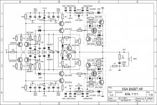
Salas Solution with a CCS in the Driver stage is a small masterpiece.... First I was sceptical but the drivers BD139 and BD140 will be able to handle all the current flowing into the basis.
He has choosen a CCS of about 2mA, I would say why not set it bit higher, like 10mA, to get a higher Ft value...
The bias circuit will have nearly optimum conditions this way, and there is no thermal runaway in the VAS stage.
PS: i am sorry, that i am not telling you guys more...
- Sonny
Someone may have asked this already, but how safe is the VAS
As safe as possible.

- Status
- This old topic is closed. If you want to reopen this topic, contact a moderator using the "Report Post" button.
- Home
- Amplifiers
- Solid State
- Simple Symetrical Amplifier