Lazy Cat please post some pictures from your work ..... same to Nico Ras .
Thanks you Alex.")
I posted few pics from the experimental phase of basic SSA, now I am in the phase to test high performance version and pics will follow. What I am after is an amp with no more than four outputs, capable of delivering some 100W and to have the best sound as possible (to mine subjective taste). I am not in a rush to make it immediately, now, that is even better since I love fiddling around the electronics stuff. The goal is always important but the road getting there is offering much more fun.

P.S. I am sure Nico will surprise us all ...
Hi Lazy Cat,
You mean to say 2SA1987 and 2SC5359 hFE should be match to be successful in building the SSA BIGBT version? If so, how close they should be matched?
How much bias did you apply on your SSA BIGBT version on post 217?
One BIGBT is having two output devices in parallel, sharing the same base current, thus forced to work even more identical concerning their collector currents. The aim is that these two output NPN/PNP devices split their hard work evenly, meaning 50:50. So ideally their hFE would be identical and Vbe too. In practice we should take care that this is realized as close as possible. But that doesn't mean it won't work if you have 20:80 hFE ratio between them, it will, meaning one of them will strugle and the other just showing off.

150mA per output device (300mA per BIGBT).
Last edited:
Hi Lasy Cat, I have to by some parts to assemble BIGBT. I have IRF couple in stock but to not made an order just to test better mosfet have you another advise as 2SK216/2SJ79?
Marc
2SK216/2SJ79 would be a perfect choice to my opinion. As I see Vds is 200V, Id 500mA, low Cgs, low Vgs treshold, very fast, high transconductance and as I understand the case is electrically isolated, so fast thermal dissipation is not an issue. They have even embeded gate protection zeners, so all in all very good, almost ideal mosfet driver for BIGBT.
Their operating current range is from 25mA (quiescent) to 75mAp (10Ap output current, NPN/PNP hFE=100), so quite relaxing working conditions.

Lazy Cat, i had send-you a PM.now I am in the phase to test high performance version and pics will follow. What I am after is an amp with no more than four outputs, capable of delivering some 100W and to have the best sound as possible (to mine subjective taste).
This is a very exciting project. I will go for it.
I wonder if we could join several members on this SACFA project (state of the art current feedback amplifier, or whatever you'll like to call-it) in order to have printed boards build somewhere in one quantity order, and silicium in numbers enough for one of us can pair them before redistribute to the other participants ?
Did-you plan to use-it as guitar amp or a studio effect ?Now, if you look carefully at the 2nd attachment you will see asymmetric emitter degeneration of the input pair. In simulations this provides a nice touch of H2 without any other detrimental impacts.
P.S. I am sure Nico will surprise us all ...
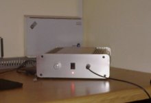
Sorry to disappoint you, mine has been in everyday use for a while
Attachments
One BIGBT is having two output devices in parallel, sharing the same base current, thus forced to work even more identical concerning their collector currents. The aim is that these two output NPN/PNP devices split their hard work evenly, meaning 50:50. So ideally their hFE would be identical and Vbe too. In practice we should take care that this is realized as close as possible. But that doesn't mean it won't work if you have 20:80 hFE ratio between them, it will, meaning one of them will strugle and the other just showing off.
150mA per output device (300mA per BIGBT).
Thanks for your reply. I'm trying to gather parts right now and would really like to try this SSA BIGBT Amp. Something really got me interested on this amp and would like to hear the sonics. Where do you buy your 2SA1987 and 2SC5359? Digikey was selling it but by bulk (100 pcs per order). Can't really afford to pay $600 for the two transistors. I might end up buying it from ebay but not sure if it's authentic.
Sorry to disappoint you, mine has been in everyday use for a while
I am glad to see it in every day's function.
Thanks for the pic Nico.
Regards, Andrej
Where do you buy your 2SA1987 and 2SC5359?
Few years ago I bought 500 pcs directly from Toshiba. Since than I have no problems with output BJT's, also because all of them have hFE around 100.
Buy them or similar ones rather from serious supplier, I heard a lot of kinky stuff coming from ebay purchases.
Thanks for your reply. I'm trying to gather parts right now and would really like to try this SSA BIGBT Amp. Something really got me interested on this amp and would like to hear the sonics. Where do you buy your 2SA1987 and 2SC5359? Digikey was selling it but by bulk (100 pcs per order). Can't really afford to pay $600 for the two transistors. I might end up buying it from ebay but not sure if it's authentic.
Fredlock, you can go with other output device. I go with MJL3281/1302 as i have them on hand. That can be 2SC500/2SA1943 that you can have good price and no fake on digikey and mouser.
Marc
Fredlock, you can go with other output device. I go with MJL3281/1302 as i have them on hand. That can be 2SC500/2SA1943 that you can have good price and no fake on digikey and mouser.
Marc
You're right Marc, I think I gonna go with 2SC5200/2SA1943, since it's cheaper and I have some of them on hand. I just need to check the hFE values. The only difference on the datasheet is the Collector power dissipation. 2SC5200 is 150W while 2SC5359 is 180W, which I think it should still be okay.
The only reason why, I want to go with Lazy Cat exact transistor version used on his amp, is to hear what exactly he heard on this amp.
Last edited:
I don't think it will be any differences. And i hope there is nothing to be heard as this amp is fast enough to be transparent if distortion is low enough. (apart damping factor ?)The only reason why, I want to go with Lazy Cat exact transistor version used on his amp, is to hear what exactly he heard on this amp.
When it was time for me to chose the Op Amps of a studio console, i had equipped different slides of the big desk with different Op Amps. One of them was all with Video curent feedback integrated circuits. It was impossible to find any difference with a strap. The differences where obvious with all the other integrated circuits. Since this day, i use exclusively CF Amps everywhere, including at home.
It was an important improvement in mixing bus (always in current), where the gain is a factor with the number of slices patched in. More desk's slices in, more gain, less speed/bandwidth with all the other circuits, while CF stays with his bandwidth and incredible slew rate unchanged with gain. With all the tension feedback here, you can notice the transients are less and less dynamic as you patch in more slices. With CF, 1 slide or 48, same sound, just an increase of noise level.
They are great too in the filter's analog circuits right after DACs where TIM is produced by circuits unable to follow the steps of the hight sampling frequencies. Even cheap DACs sounds suddenly transparent.
We have to notice that the first remarkable thing to hear, with fast amps, is the quality of the basses. They sound suddenly more warm, dynamic and damped in the same time. And, strange but true, treble softness. You can even feel than you have lost level here. But it is not. The are just more airy, less aggressive, more fluid, with a perfect sound stage.
My power amp i use since 20 years now was build following the Current Feedback ideas of Mark Alexander at Analog Device. I had never heard a better amp since this time. And i'm sure this SSA will perform as well and, once distortion level will be reduced to the limits (Dual matched pairs ?, More current margins ?, DC servo ?etc), even slightly better, because this nice and so clever first stage.
Sorry to be so noisy, but i would like to share some ideas i have or had.
Here with speakers protection.
Well the first one is the traditional relay in serial with output. could-it be better replaced with 2 (on/off) power moss in the supply lines of the last stage (where the fuses are ) for they do not add a inline resistance with the loudspeakers reducing the damping ?
Well, this need an idea to be found in order to connect the feedback loop when they will be in their "off" stage.
A second parallel low current last stage, switched when protection is on, and witch could be used too as a headphone output ?
The other idea is the command of the protection. Instead those complicated circuits witch integrate signals in order to detect DC on the output, my 25years old idea was to simply compare input and output signals of the amp. When something is wrong, DC in the output, HF, clipping, output short circuit, whatever, you will have a differential signal you can use for protection after accurate hysteresis/delay treated on a separated protection board common to all the amps.
It works like a charm in my own amp. The best place to build this comparator is on the AMP board itself. A simple OP amp witch compare input and output signals once the gain has been scaled. Then, the output will be available for the main protection circuit, isolating the amplifier and simplifying the all stuff. And you just are not obliged to solder-it if you do not want it.
The too ideas come together, as this comparing process is so fast that i believe the power moss ( in the power lines) will not have time to burn or heat in case of short circuit.
Lazy cat, it is up to you if you like to consider those ideas.
Shaan,
Nice circuit.
I would, however, delete Q10 and Q11 and simply link CE on Q5 and CE on Q2; this will create the current mirror you need here.
However, why not simply delete Q10/11 as above and also Q5 and C2, realying instead on conventional base drive on Q6 and Q3? This is simpler, and saves four devices.
I'd suggest you run Q1 and Q4 at around 4mA each and change R14 and R15 to around 150R. I think R22 is probably not required either; replace R1 and R2 with a single 8K2 resistor, insert a 220K ground referencing resistor at the upper output of the siggen, and alter the upper 47K resistor of R3a/b (see below) to set output offset. R20 and R21 would then be around 68R each.
I would also split R3 and R4 into four 47K resistors, with a large electro from the junction of the 47K resistors to ground to decouple the input bias network from the power rails.
The output stage will work very nicely but you won't need a bias generator - just a variable resistor - if you set output quiescent at more than 200mA.
Cheers,
Hugh
Hi
Replace R3/R4 with CCS, a few mA at least, adjust R1/R2 to accommodate bias. Take the input to R22. The mirrors with the helper transistor should be fine just add a resistor from the emitters of Q10/Q11 to the rails. This way they are conducting more than just the tiny base currents of Q's 2/3/5/6. Maybe a base stopper for Q3/Q6. A practical design might include a zero (~30MHz; 120R in sereis with 47pf) from gate to drain of the output mosfets.

Replace R3/R4 with CCS, a few mA at least, adjust R1/R2 to accommodate bias. Take the input to R22. The mirrors with the helper transistor should be fine just add a resistor from the emitters of Q10/Q11 to the rails. This way they are conducting more than just the tiny base currents of Q's 2/3/5/6. Maybe a base stopper for Q3/Q6. A practical design might include a zero (~30MHz; 120R in sereis with 47pf) from gate to drain of the output mosfets.
Last edited:
I've explored a couple of options in the simulator.
Attached first/left is the same version I posted above for an all-BJT version. [Note that my amplifiers are named TGM1, TGM2 etc. and as this is my 5th amp I'm labelling it TGM5]. It's a simple double EF output with the LazyCat SSA input. Works like a charm in the sims. No turn on bumps either. I take my hat of LC for this simple solution for symmetrical CFB.
Attached second/right is amodified version, I've taken the cascode devices and flipped them to the output stage. The result is a CFP driver. This design is now effectively a simple symmetric version of my TGM3 amplifier. The high current zener bias stage disappears and instead the feedback node is biassed from the rails (suitably decoupled). Is this still the SSA anymore if I do that so the question is - just because I can, does it mean I should ?
The CFP driver reduces distortion for both versions of the front end.
My simulations show the need for compensation - at the least it requires miller compensation on the VAS. It doesn't need much and the OLG retains an extended region of low phase shift - this thing really is a vhf amp.
Lastly, I noted in my sims that H3 is slightly higher than H2 - contrary to what has been reported for the LatFet output version. I expected a symmetric amp to have more H3. I can only assume, still, that higher H2 comes from device mismatch.
Now, if you look carefully at the 2nd attachment you will see asymmetric emitter degeneration of the input pair. In simulations this provides a nice touch of H2 without any other detrimental impacts.
Nice you have stumbled upon one of the circuits Ive used for nearly 20 years. The circuit will sound very good even without the H2 injection. The only difference is that I use feedback from the vas only, CFP vas and the output stage is openloop. Its my favourite headphone amp too although the vas is the outputstage. This circuit was first used by JLH circa 1976 and in its simplest form can be seen in the JLH MC preamp, Rega has also made use of this circuit. The higher H2 from Lazycats circuit comes from the input transistors being biased at lower Vce and because of the early effect causes higher THD especially H2.
Have a look at Lineup s posts of a couple of months back, there he shows the simplyfied version of this amp in a thread he started.
- Status
- This old topic is closed. If you want to reopen this topic, contact a moderator using the "Report Post" button.
- Home
- Amplifiers
- Solid State
- Simple Symetrical Amplifier