............. using a high value resistor to shunt that charge to audio return/ground/cold. This also works if the capacitor leaks a little. Typically Builders use anywhere from 100k to 2M2.
...............
I use 2M2 and this works for any plastic film input capacitor.....................Hints for how to work out value of grounding resistor?...........
If you have a capacitor that leaks badly, you will need a much lower value.
That may explain why we often see 100k and lower being used.
")
Reduces the number of active interference loops !and what's the benefit of being able to switch the ground?
this is what the manual says:
"Position 1 Both channels keep common ground and both are connected to the chassis of TRUE
Position 2 Channel A and Channel B keep separate ground to output A and B without connection to TRUE chassis
Position 3 Both channels keep common ground to outputs without connection to TRUE chassis"
under what circumstances would one choose those settings?
so you don't think this would be the best of designs? did i read that right?
what about this way of wiring it .... better approach?
what about this way of wiring it .... better approach?
An externally hosted image should be here but it was not working when we last tested it.
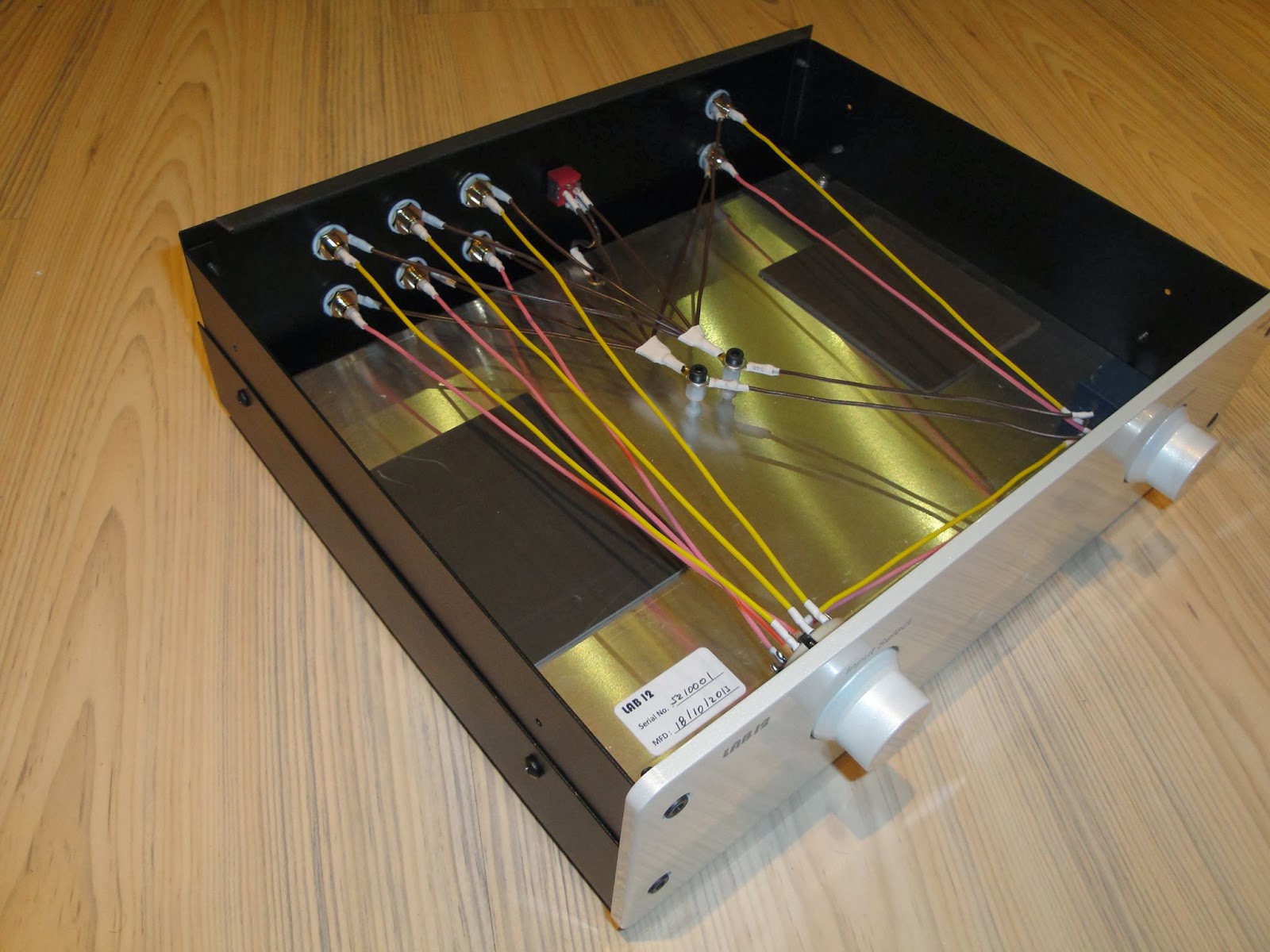
Actually it is a good example of how not to do it. I hope it is cheap.Mixi said:i just found this. no idea if it makes sense, but it sure looks good....
Yes, much better.what about this way of wiring it .... better approach?
i'm still rather new to this whole diy audio thing but i do get the impression that some of the commercial products out there are really bad designs
....i assume some of you reached that conclusion much sooner than me.
Maybe because the assemblers have little knowledge and are not Members of this Forum.
this is the circuit drawing of the passive amp from post #50. could this be the right approach for a good passive?
An externally hosted image should be here but it was not working when we last tested it.
Yes. For really poor design you need rather cheap or very expensive items. Mid-price items are usually well designed, as are some expensive items.Mixi said:i'm still rather new to this whole diy audio thing but i do get the impression that some of the commercial products out there are really bad designs
- Status
- This old topic is closed. If you want to reopen this topic, contact a moderator using the "Report Post" button.
- Home
- Source & Line
- Analog Line Level
- simple passive preamp