... Does anybody sell 1 or 2 pcbs in Europe or Brasil? Kits are also fine! 🙂...
PM sent 🙂
Mark,
I measured about 5-6 my transformers by now (all are toroids and one is R-Core 30VA) and all measurements are directing me to use resistors in range of 5-10 Ohm. I see guys used here 120 Ohm and some times higher values for some tranys. I curious my be I'm doing something wrong...? I use 18v DC for our jig and try to copy your procedure correctly... Please advise.
Sent from my iPhone using Tapatalk
Every time someone posts this request, I give the same answer: If you don't like or don't trust the no-math answer, your only alternative is to use math.
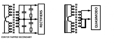
I suggest you begin this effort by measuring the leakage inductance of the transformer secondary (in Henrys) with each primary winding shorted and with each other secondary winding shorted. These shorts are shown as heavy black bars in Fig 13.d of the Quasimodo design note.
Once you know the measured value of the secondary leakage inductance, and once you know the values of Cx and Cs you will use to snub it, then you can calculate the value of Rsnub which gives zeta=1.0. If the calculated value of Rsnub equals 5-10 ohms, everything checks out.
Mark,
I'm not questioning jig performance and I'm sure it is 100% functioning correctly. I doubt my actions. I might do not use scope correctly. I'll try to use math for my tranys for compare and let you know..
I'm not questioning jig performance and I'm sure it is 100% functioning correctly. I doubt my actions. I might do not use scope correctly. I'll try to use math for my tranys for compare and let you know..
So, my math is below:
C trany = 240pF
L trany = 268.9µH
Cx = 0.01µF
Cs = 0.15µF
MUR120 C rect ∑ ≈ 50pF
Caps on rect-diodes = 0.022uF
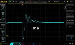
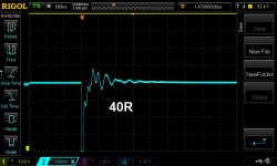
Calculated Rs = 91.3R
On my Jig, I see about 40R is the best for no ringing on that trany.
Can you please check if my math is correct?
C trany = 240pF
L trany = 268.9µH
Cx = 0.01µF
Cs = 0.15µF
MUR120 C rect ∑ ≈ 50pF
Caps on rect-diodes = 0.022uF
Calculated Rs = 91.3R
On my Jig, I see about 40R is the best for no ringing on that trany.
Can you please check if my math is correct?
Please see attached pictures and correlated param files.
May be I'm not doing that right...
May be I'm not doing that right...
Attachments
Last edited:
Alexkosha, it appears you have misconfigured your scope probes AND misconfigured your CH1 & CH2 settings
Did you notice that photo#1 of post 706 says (upper right) that you are triggering the waveform capture, when channel 1 rises through +79.0 volts? That seems very unlikely to me, since you are powering your Quasimodo from a DC source less than 20 volts -- probably a 9 volt battery. Where oh where are you able to find +79 volts in a less-than-20-volt circuit?
I recommend that you invite a friend who earned a four year Bachelor of Science degree in electrical engineering, over to your house for pizza and beer. Halfway through the meal, ask her to show you how to set up your probes AND your CH1 & CH2 settings. Ask her how to hook up a probe to the calibrator and then use the AUTO feature to make the scope automatically set its vertical and horizontal systems to something approximately decent.
(Your .txt files say that CH1's settings include 10X attenuation, but channel 2's settings include 1X attenuation. One of these is wrong.)
After you've got your oscilloscope probes configured correctly, and after you've got your oscilloscope's CH1 and CH2 settings configured correctly, I recommend you perform the confidence-building Quasimodo experiment described in post #487 of this thread. Then read post #257 of this thread.
To my simple brain, it seems like a couple of LEDs could be configured to light up, one for positive swing output and one for neg. swing, and adj. until both light up for the min. amount of time. Is my brain too simple?
Maybe the commercial product shown in Figure 15 of the Quasimodo design note, is exactly what you want? It's ready to go and on the shelf today, waiting for your credit card payment.
(Design note is a .pdf file attached to post#1 of this thread)
(Design note is a .pdf file attached to post#1 of this thread)
I did read it. I think it might be more fun to play with the idea and see what I can come up with! Since i am not "schooled", I'll probably do some fumbling, but what the heck...
A quick google search revealed more than one way to skin the cat, and therefore, more than one circuit schematic. I grabbed this photo of one person's build, of the "Dick Smith Australian" design variant; it's quite well constructed.
_
_
Attachments
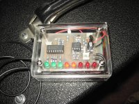
A quick google search revealed more than one way to skin the cat, and therefore, more than one circuit schematic. I grabbed this photo of one person's build, of the "Dick Smith Australian" design variant; it's quite well constructed.
_
If I understand correctly, on this device what they consider "bad" is the outcome we seek. I should build one and see what result ends up in approx. 120ohms. That seems to be the ballpark.
Many Quasimodo users find it enjoyable to dial the potentiometer and watch the ringing grow and shrink on the scope. Hey look, Ma: I'm controlling the transformer ringing!
This same desire for human stimulus ---> visible electronic response, might carry over to your scopeless device. People might WANT to jockey with a knob and watch the LED indicators change.
This same desire for human stimulus ---> visible electronic response, might carry over to your scopeless device. People might WANT to jockey with a knob and watch the LED indicators change.
Indeed, that is one of the joys of doing this stuff.
Plus, scopes are better for recruiting grandchildren than LEDs in my house
🙂
mlloyd1
Plus, scopes are better for recruiting grandchildren than LEDs in my house
🙂
mlloyd1
Many Quasimodo users find it enjoyable to dial the potentiometer and watch the ringing grow and shrink on the scope. Hey look, Ma: I'm controlling the transformer ringing!
...
Indeed, that is one of the joys of doing this stuff.
Plus, scopes are better for recruiting grandchildren than LEDs in my house
🙂
mlloyd1
Wow, you mean if I had propagated my specie with a couple of little environmental disasters, and they had followed suit, I could justify buying a scope to the missus? Had I only known!
Does anyone have a fully assembled Quasimodo board to sell? How about a bare Quasimodo board plus kit of all parts, to sell? If so then diyAudio member kenlaumm would be thrilled if you sent him a Private Message.
At last I tested my 30VA 12+12 r-core transformer with beautiful Quasimodo. Got some results and just want to check them with you guys. Amplifier, which transformer I'm upgrading, already has Cx capacitor installed - 0.47µF. So I chose Cs=4.7µF (Cx x 10) for my snubber and plugged trafo with capacitors into the Quasimodo. Quasimodo was powered from 9V battery. Without Rs, calculated ζ was 0.026. By winding down Rs from 1kΩ to ~10Ω I got desired ζ=1. Does this Rs seem low to you? Manual for the Quasimodo name some Rs values and they are in 100-200Ω range. Also, LTspice simulation showed that 10Ω Rs will dissipate no more than 6mW in my configuration.
- Home
- Amplifiers
- Power Supplies
- Simple, no-math transformer snubber using Quasimodo test-jig