Well,
All my work last night goes out the window if we are fairly sure we want a gain of over 10.
Here's the "Quandary":
Goal is to take a relatively low level signal (in Daniels case a PC sound card or I-Pod) and Amplify it with a Tube, this will impart some of the "tube sound" into the signal. Since the tube is going to have significant gain, any gain in the chip circuit MULTIPLIES that gain. Now for Daniel, a gain of 20 is probably not all that bad since he is looking for a total gain of 50 or so.
500mV x 50 so if we can keep the tube to about a Gain of 3 then we are Ok.
Tubes do not like to be run with such small loads, voltages and currents.
One option might be to NOT amplify the signal but simply put in a phase inverter (Split Load) which has almost Unity Gain (but since we are splitting into to Inverse Signals it has the effect of a gain of about 2)
In may case I have a preamp that is feeding about 2V RMS signal so I REALLY cannot afford too much gain. But If we use the tube inversion method I can keep it under control.
What is the thought of using a gain of about 17-18 on a NON-Inverting Parallel configuration?
So , at the end , you're going with this set , right?
1) huge SMPS for both channels
2) bridged LM 4780 , so 2 LMs , not 4 ?!?
HUGE SMPS yes
There will be FOUR 4780 chips for TWO channels.
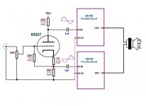
Think of it like this
The signal comes in and enters the Grid of a Triode Tube.
I take an "in phase" signal from the Cathode and an "Inverted" signal from the Anode (plate) They are identical except for phase and the amplitude will be about 90% of the input.
So overall we get a gain of about 1.8, the signals will be fed to LM4780's in parallel on their own boards.
The outputs of the Pairs will be "Bridged" to the load.
see attached
Attachments
Practical Examples (known good):
1). http://www.diyaudio.com/forums/chip-amps/155375-my-new-baby-tbgc.html
2). Building a valve-buffered Gainclone chip amp.
Technical Op Amp materials (mostly read-able):
1). http://www.en-genius.net/includes/files/acqt_013105.pdf
2). http://www.national.com/an/AN/AN-20.pdf
Thermal usage (applied to 4 ohm loads):
Also compare the thermal interface of a paralleled pair of LM3886 versus a paralleled LM4780 and calculate for 4 ohm speakers. LM3886 can do bpa200 for 4 ohm speakers, which may be more seemly design than frying LM4780's; however, on 8 ohm loads exactly matched LM4780's may run cooler because of the matching, but it remains true that the LM4780's thermal disadvantage can easily outweigh the benefit of matching (as there may or may not be matching, but there is for certain an inappropriate thermal interface).
Last edited:
The move towards parallel is wonderful thing and its going to make this so much easier, as well as considerably more rewarding. The tube bridge driver idea is fantastic!!
The datasheet LM3886 is for an extra loud television, and so we need to avoid doing it that way because the Acutance - Wikipedia, the free encyclopedia peak occurs in the range of the female voice needing an equalizer rather than at the baritone where it could be controlled by power circuit options. We need to plan on making an amplifier that facilitates reproducing your tube sound efforts, and thus this amplifier must reproduce much more faithfully than the datasheet LM3886 example.
The datasheet LM3886 is for an extra loud television, and so we need to avoid doing it that way because the Acutance - Wikipedia, the free encyclopedia peak occurs in the range of the female voice needing an equalizer rather than at the baritone where it could be controlled by power circuit options. We need to plan on making an amplifier that facilitates reproducing your tube sound efforts, and thus this amplifier must reproduce much more faithfully than the datasheet LM3886 example.
Last edited:
However, I have no choice other than to pick the tallest waveform (overcompensated)
Actually that's undercompensated. It's even written below each screenshot
")
LM4780 is a double LM3886. Really, it has two dies which are the same as the one in LM3886. That explains why it runs hot.
This idea with a phase inverter is excellent, it will work very nice. If you don't keep the volume at 40W/chip the sound will be really nice. coldcathode, what's the sensitivity of your subwoofer?
Subwoofers have not been decided on 100% right now. I do have some "Automotive" woofers with a about 88-89db/1W 1M.
I really do not see me driving them at more than 50 Watts total per channel (25/chip)
The idea of using the 4780 is mostly because of the availability of ready made gold plated PCB boards and ease of wiring.
This layout I think is overall the "optimum" design for bringing the tube and the chip together. Point to Point is an option but would be rather difficult with 4 chips per channel. I like the layout of the PC boards and Zobel components can be added later if I feel the need.
I look at it as, each board is essentially a parallel pair of power triodes. As I delve deeper into system design and loudspeaker design I might even go as far as raising the Low pass point of the crossover at the front of the system and then run a "Subwoofer" channel and a "Woofer channel". Letting a pair of 8" woofers roll off naturally below say 60hz with an upper low pass of 200-300hz, I can insert another lowpass in this amp to put the subs at 80 hz and down.
National have reason to tell us how to operate their chipamp.it turns ugly - heavy oscillation.
So gain below 10 is not really a viable option.
Gain of >=10 is specified for a reason.
Many builders tells us that it sounds best if the gain is between 20times (+26dB) and 30times (+30dB). a few settle for either 23times or 27times as the best sounding.
There is one 3886 schematic that is configured very differently from all the others. It seems to operate the chipamp at low gain and the opamp at higher gain. I wonder if this unusual feedback composite could be applied to this hybrid proposal?
you are going to have to be more precise.Subwoofers have not been decided on 100% right now. I do have some "Automotive" woofers with a about 88-89db/1W 1M.
Are these "automotive" drivers 4ohm or 8ohm?
Are they 88-89dB/W @1m or 88-89dB/2.83V @1m or 88-89dB/2V @1m?
A pair of 3886 chip will perform better than a 4780.
A 4780 operated in bridged mode will operate better than a 4780 operated in parallel mode.
Choosing to use 4780 in parallel mode guarantees the poorest performance of all the options.
If you must use the 4780 then adopt bridged on the one chip. Then parallel as many as needed to suit the driver load and PSU voltage.
+-28Vdc and bridged will work badly into 4r0 and even worse into 4ohm.
+-28Vdc and bridged will work reasonably into 8r0 and poorly into 8ohm.
+-28Vdc and bridged will work well into 12r0 and reasonably well into 12ohm.
+-28Vdc and bridged/paralleled (BPA200) will work well into 6r0 and well into 8ohm.
+-28Vdc and bridged/triple paralleled (BPA300) will work well into 4r0 and well into 6ohm. It may perform well into 4ohm but you are stretching it when you read the specifications.
Lots of options to experiment with.
As far as the subs,
I have two Alpine Subs (older) they were never used.
They are (I have to dig up the spec sheet but..)
88.7dB @ 1W 1Meter.
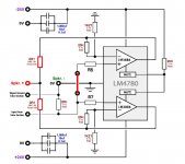
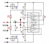
I have chosen a gain of about 18 for the chip amp.(20K/1K21)
The configuration is basically like that shown in Fig 7 of the BPA200 sheet.
Except that the bottom pair (LM4780) is not Inverted. The signal feeding it is inverted.
Supply will be 24V + or -
Load will be 4ohm or higher possibly as I design the system.
The performance is not the best, but the configuration, ease of build, availability of reasonanble priced boards, ect fits my requirements.
I have two Alpine Subs (older) they were never used.
They are (I have to dig up the spec sheet but..)
88.7dB @ 1W 1Meter.
I have chosen a gain of about 18 for the chip amp.(20K/1K21)
The configuration is basically like that shown in Fig 7 of the BPA200 sheet.
Except that the bottom pair (LM4780) is not Inverted. The signal feeding it is inverted.
Supply will be 24V + or -
Load will be 4ohm or higher possibly as I design the system.
The performance is not the best, but the configuration, ease of build, availability of reasonanble priced boards, ect fits my requirements.
you still have not told us if the "alpine" drivers are 4ohm or 8ohm. You have not confirmed if the sensitivity is /2V or /2.83VI have two Alpine Subs (older) they were never used.
They are (I have to dig up the spec sheet but..)
88.7dB @ 1W 1Meter.
These two pieces of information make a BIG difference to the design of your proposed chipamp.
Andrew with all due respect the specifications of the woofer should be irrelevant to the overall design of the chip amp. The impedance of these particular woofers is 4ohm. (3.1 DCR)
Unfortunately in the "old days" of car audio (where I have extensive experience) sensitivity was rated at 1W @ 1Meter. This in a 4ohm woofer cannot be directly correlated to a voltage. Since we lack 1 of the variables to calc the other. In addition the spec never specified a frequency so they obviously chose something that helped "sell" the woofer.
I appreciate your help and wanting all the information to assist my overall choice. My decision to use this topology is as much about preference and aesthetics as it is properties and "ideal" performance.
Correct me if I am wrong but the parallel pair "sees" double the load presented to its output correct? So each have of the chip sees the same load. The bridged sections then see half the load so 2ohms.
Each of the 4 sections of chip are now operating into a 2 ohm load which is not ideal but since we are halving the current is should be OK?
As it is I feel the tube amps will run into serious trouble keeping up with the subs at the ear splitting levels available with this sub amp.
This amp should be able to deliver over 110dB output with those subs at less than 2%THD. As I go forward in the system design and component aquisition I will go with 8 ohm or even 16ohm woofers.
The design is something that will "work OK for now" but "better later".
This amp should be able to deliver over 110dB output with those subs at less than 2%THD. As I go forward in the system design and component aquisition I will go with 8 ohm or even 16ohm woofers.
The design is something that will "work OK for now" but "better later".
It appears we have come "full circle" on this project. At the outset I intimated that my experience and preference is Vacuum Tube amplification. My reason for approaching a "chip amp" was purely because I feel I cannot afford to build a 50WPC into 4ohm Tube amp with distortion under 5%.
Most certainly to approach that level in tubes I need to go with Push Pull "Ultra Linear" Pentodes probably KT-88's
The TUBES ALONE cost $55 - $100USD each! x 4 is probably double what this project will cost me in total. A decent pair of Push Pull UL Transformers would add an additional $250-300USD. So I could easily spend over $2K USD to complete a 50WPC "clean" tube amp and still probably not equal this performance in the limited frequency range I plan on.

I suspect the sensitivity is actually 88.7dB/2.83V @1m rather than 2V for 1W into 4r0.with all due respect the specifications of the woofer should be irrelevant to the overall design of the chip amp. The impedance of these particular woofers is 4ohm. (3.1 DCR)
The actual sensitivity may be ~86dB/W/m. To get 110dB @2.5m from a pair of these you need ~850W per channel into 4r0.
Now to the chipamp datasheets.
The load impedance is critical to the design of the chipamp.
You must select supply voltage and heatsink capacity based on load impedance and desired power target.
The advantage to using +-24Vdc to drive a 4ohm speaker from a parallel set up is that the heatsinking requirement is much lower and this will suit the 4780 better due to it's inherent lack of ability to dissipate heat to the sink. A parallel 4780 will need about 1.8C/W @ Ta=25degC.
If you decide to bridge a pair of these paralleled 4780 the whole ballgame changes. Instead of each amp seeing 8ohms as it's speaker load they each see 4ohms and each 4780 now needs 0.7C/W and will be noticeably hotter than the simple paralleled device. But for this the power increases from ~40W/channel to ~120W/channel.
Last edited:
- Status
- This old topic is closed. If you want to reopen this topic, contact a moderator using the "Report Post" button.
- Home
- Amplifiers
- Chip Amps
- Simple Chip Amp for P to P wiring