sekanix said:
I deleted one diode
because the output stage was getting much more heat and
the standby current was 2,5 times bigger (150mA aprox.)
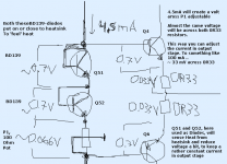
Start with trying to get ~100mA across each 0.033 resistor.
It has been proven to be a good value. To start with.
Gives 0.033 Volt ( 33 milliVolt across one 0R33 )
How to keep the current, like 100 mA,
even when amplifier play loud music = heatsink gets warmer ??
Here is my basic advice.
How we can do this .. still keeping things very simple.
Replace the D2-D5, with what I show in attachment figure.
I think you will understand well
")
There are notes, text in my little diagram.
If you have questions about this way I recommend (for a good first try)
Just Ask ... we are several here that will be able to explain further.
Lineup
thinks sekanix has a very good amp coming!!---------------------------------------
---------------------------------------
(There are more sofisticated, advanced methods to try keep steady (~100 mA e.g) current in output.
But this way I show, will work.
And what is more important: It will make you understand what happens.
Shown in a very, very basic way )
Attachments
but the CFP is also more prone to oscillate.
A CFP requires much less emitter resistor voltage than an EF output stage for optimum ClassAB bias.
For EF use between 15mV and 25mV across each emitter resistor.
For CFP use between 2mV and 5mV across each emitter resistor.
D.Self says 5.6mV across a pair of 0r33 emitter resistors.
That will give ~6mA through the drivers and ~2mA through the outputs.
AndrewT said:
D.Self says 5.6mV across a pair of 0r33 emitter resistors.
That will give ~6mA through the drivers and ~2mA through the outputs.
Yeah, good for you AndrewT.
You try with 8 mA idle in your amplifiers.
I have a slight remembering you were about to publish you power amp project in a Topic.
You were exploring ways to attach schematic of your amplifier.
Anyway, Good luck old audio comrade
------------
To get optimal value in Class AB amplifier, we need an oscilloscope.
To observe crossover distortion, at different power levels and at different audio frequencies.
But .....
The general observation people have made, trough the years is:
That something like 50-120 mA is, most amplifiers, the 'ideal' compromize.
( I am talking BJT power devices here.
Sekanix is using BJT. MOSFET are a bit different. But not too much different )
--------------
It is also about what we are after, what we want:
1. A minimal idle power consumtion = Class B, or very close to Class B
Like AndrewT prefers in his amplifiers.
2. The most used compromise: Class AB. Which I am talking about.
Works in Class A at the low power levels. The levels that are maybe 80% of 'normal music listening'.
Turns into Class B at higher power levels, and music peaks.
3. Class A.. The champion!
Works in Class A in most all power levels.
The idle current is set to cover a nominal max power level in some specific loads.
Usually expressed as True Class A into
4 Ohm and 8 Ohm
lineup said:
Start with trying to get ~100mA across each 0.033 resistor.
It has been proven to be a good value. To start with.
Gives 0.033 Volt ( 33 milliVolt across one 0R33 )
How to keep the current, like 100 mA,
even when amplifier play loud music = heatsink gets warmer ??
Here is my basic advice.
How we can do this .. still keeping things very simple.
Replace the D2-D5, with what I show in attachment figure.
I think you will understand well
There are notes, text in my little diagram.
If you have questions about this way I recommend (for a good first try)
Just Ask ... we are several here that will be able to explain further.
Lineup
---------------------------------------
---------------------------------------
(There are more sofisticated, advanced methods to try keep steady (~100 mA e.g) current in output.
But this way I show, will work.
And what is more important: It will make you understand what happens.
Shown in a very, very basic way )
I understand perfectly your explanations, many thanks for it. I will make this mdofication and then measure all voltages and output stage current.
Regards!
Agreed, most of my amps are EF and for these 15mVre to 25mVre gives optimum bias for ClassAB in an EF output stage. This equates to 45mA to 75mA for Re=0r33.lineup said:.............The general observation people have made, trough the years is:
That something like 50-120 mA is, most amplifiers, the 'ideal' compromize.
not what I said and your statement is completely opposite to what I believe and do.lineup said:
1. A minimal idle power consumtion = Class B, or very close to Class B
Like AndrewT prefers in his amplifiers.
Go back and re-read post22, it says:-
For a CFP output stage the Vre requirement for optimum ClassAB is much less than for an EF stage.
This lower Vre does result in much lower output stage bias and does indeed result in very cool running heatsinks, but when set up for optimum ClassAB, it most definitely is not ClassB. A CFP output stage runs the drivers in near constant current mode for very low output to quiescent operating conditions. The output device turns on harder when more current is required by the load.
yes, if you arrange for speaker sensitivity and amplifier power levels to give a peak transient SPL capability of around 20dB above the average listening level then your power amps will stay within the ClassA current of an optimally biased ClassAB EF output stage. i.e. 100W amp ticking over at 1W of average power will stay in ClassA for all output currents below 500mA (1W into 8ohm) if the optimum bias needs to be set to 250mA (2pair through 0r18 emitter resistors).lineup said:
2. The most used compromise: Class AB. Which I am talking about.
Works in Class A at the low power levels. The levels that are maybe 80% of 'normal music listening'.
sekanix said:
I understand perfectly your explanations, many thanks for it. I will make this mdofication and then measure all voltages and output stage current.
Regards!
I would have used a VAS cct to get the output bias correct.
I would also add a VAS constant current cct to the negative rail.
In my first amp build I just used resistors and found I couldnt get a good voltage swing on the output. The VAS constant current cct will pull it hard up to the rail.
AndrewT said:
Go back and re-read post22, it says:-
For a CFP output stage the Vre requirement for optimum ClassAB is much less than for an EF stage.
This lower Vre does result in much lower output stage bias and does indeed result in very cool running heatsinks, but when set up for optimum ClassAB, it most definitely is not ClassB. A CFP output stage runs the drivers in near constant current mode for very low output to quiescent operating conditions. The output device turns on harder when more current is required by the load.
thanks for reply Andrew
on second thought I have to agree with your points
things are a bit different in sziklai CFP, complementary fold back
Your Doug Self reference is most interesting.
Eventhough the man likes to be controversial, against others,
he has some points regarding Output stage idle bias, as well as emitter resistor values for Output devices.
As I have got his message:
Biasing output stage (BJT) only as much to remove CrossOver distortion
(usually requires much less than 50-100mA)
gvies a good working output stage.
Because this deals 'prefectly' with when the postive (NPN) transistor
stops conducting, and leaves the job over to the PNP.
Contrary to what many believes, a Class AB biased at higher current, say 100mA,
will worse overall performance, than an 'optimal' biased Class B, at a few milliampere.
The critical area in this Class AB 100 mA, comes around 200mA output.
This is where AB is transiting into Class B.
Here the low biased (near to Class B) is probably behaving BETTER.
So to sum it up:
-------------------------
* True Class B, no bias, will have crossover distortion.
* The very low, optimally biased Class AB will have best overall performance, of the non-Class A.
The bias will reduce crossover to a minimal.
* Class AB, biased 100mA, to operate at Class A upto ~200 mA
will have worse performance at this specific critical level, than optimal biased.
* Class A, will not have such problems, but will have other issues and drawbacks.
As Heat and Cooling management and Power Supply quality.
regars
lineup .. formerly known as 'gromanswe' and 'groman'==========================
References and further reading:
John Curl, january 2002:
Re: Surprising fact: B better than AB!
http://db.audioasylum.com/cgi/m.mpl?forum=tweaks&n=50365
Douglas Self website
Distortion In Power Amplifiers.
Updated: 9 Oct 2001
http://www.dself.dsl.pipex.com/ampins/dipa/dipa.htm
# Fig 20 Crossover distortion with output stage underbiased by varying amounts. Lowest curve is for optimal biasing, and is essentially noise. #550
# Fig 21 Crossover distortion at increasing frequencies for EF output stage. Note low-distortion area below -15 dB. (ref 25W/8 Ohm) #551b
# Fig 22 Crossover distortion at increasing frequencies for CFP output stage. Low-distortion area is absent. #552b
# Fig 23 Crossover distortion under light loading. 68 Ohms is sufficient to produce measurable crossover. #541a
timpert said:Sekanix,
Did you already manage to do something with your amp?
Hello,
It was a difficult weekend, so I think today I will be able to make all mesurements and attach the photos
sorry...
AndrewT said:Hi Lineup,
I think you have already realised that D.Self has his own definition for ClassB and it is exactly equal to what most others refer to as optimised ClassAB. By optimised we mean minimal crossover distortion.
we should not mind terminology and expressions like 'Class' too much
because these terms, in the mind of people, can mean different things
.. as with any words.
words are 'symbols' for thoughts
What a word like 'love' means to any individual, in a given context,
depends on 'brain associations'
Instead, it is better to actually describe Output bias level,
and a practical case/situation with plain words and electrical data.
This way we know better what we are talking about.
We are on talking terms, so to say
regards
lineup - prefers not to use swedish terms & words .. in this forum.. because might not trigger the correct associations in english-speaking & chinese-native minds
This topologie sounds good...it is a nice starting point
Well....i have tried many thousand units.... and i continue to love this kind of circuit.
In my life it is more an ending point than a starting point..... i use to return to listen that kind of circuit, as i love the sound colourations.... i have checked many... and i still love to listen this one...alike this one..... having some small add on.
If you have listened, as i have not readed all thread, was lucky, as already have experienced a very nice quality of sound reproduction....an excelent starting point..... i have travelled with many topologies and returned to this one....my starting point turns my ending point.
The excelent Aksa amplifier use this topologie.... of course have sub circuits and special tuning...special selected parts and different feedback ideas...but the "spirit" of nice sonics remains into the bootstrapped ideas (my point of view, my opinnion)
I have made one, the Dx Amplifier.... not so good as the Aksa amplifier, but sounds very nice too...it is hard to kill this topologie sonics... even if you are bad into designs this nice circuit produces some nice effect.
In this link you can see the same topologie you suggested... made in China.... and the interesting is that measure very well too...good to instruments too.... you can see some wave forms into the pictures.
http://bbs.hifidiy.net/viewthread.php?tid=108127&extra=page=1
regards,
Carlos
Why 100r resistors are rated 1W? They are dissipating only a few mW!
About the diodes... let's calculate!
60W/8r>3.9Apk>1.3V on 0.33r.
Vbe for drivers is 0.7V at ~100mA.
1.3V+0.7V=2V.
But the serial diodes will cut at ~1V...
Anyway this circuit is from an old Motorola handbook.
The schematic was really popular in the socialist countries in Europe (Bulgaria, Romania, Chezslovakia, etc.).
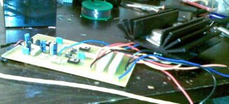
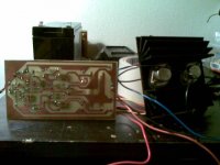
Some photos of the finished and working amp
Hi guys,
I have finished the PCB and mounted the amp on it. Now it works fine. I connected a BD139 transistor with base-collector shortcut instead of bias diode, and now 65mA of iddle current on output stage. The amp sounds great without any more modification, and I'm testing it with 40V and it works fine, the only thing is to change BC547 to BC546 and increase the voltage to 45V, and then try to connect 2 MJ15001/2 more to increase the power (I dont sure if will works, any suggestion is accepted
So here's the fotos:
Attachments
... diodes... let's calculate!
60W/8r>3.9Apk>1.3V on 0.33r.
Vbe for drivers is 0.7V at ~100mA.
1.3V+0.7V=2V.
But the diodes will cut at ~1V...
You will get really huge distortions... > bad sound!
Andy L. Francis said:
You will get really huge distortions... > bad sound!
You mean the BIAS diodes or protection diodes?
What do you think, can I remove protection diodes without any danger for the output stage? I'm not sure...
Thanks!
Re: Some photos of the finished and working amp
Good work sekanix!
I dont know why you want to INCREASE power ... ???
Are you not happy with 36 Volt and one pair MJ15001-MJ15002.
I build amplifiers with +-16 and +-20 Volts and they give all the power I need for my speakers.
It will not make your amplifier better, to add more output devices & more voltage.
To manage more output currents -> you need more driver currents.
And more driver currents may need -> more VAS power.
More VAS power may require -> stronger input transistors currents.
The baseline is:
you will most probably need to change every stage in amplifier.
To keep a fair Quality at a higher Quantity.
This is not same good amplifier no more.
It is a new amplifier project.
You can Build yourself Amplifier no. #2.
But let this good one be your successful no. #1
I say enough is enough
Be happy and try to improve QUALITY at the power you have now HAPPILY working.
'More' is not same as 'Better' ...
sekanix said:Hi guys,
I have finished the PCB and mounted the amp on it. Now it works fine. I connected a BD139 transistor with base-collector shortcut instead of bias diode, and now 65mA of iddle current on output stage.
The amp sounds great without any more modification, and I'm testing it with 40V and it works fine,
the only thing is to change BC547 to BC546 and increase the voltage to 45V,
and then try to connect 2 MJ15001/2 more to increase the power (I dont sure if will works, any suggestion is accepted
Good work sekanix!
I dont know why you want to INCREASE power ... ???
Are you not happy with 36 Volt and one pair MJ15001-MJ15002.
I build amplifiers with +-16 and +-20 Volts and they give all the power I need for my speakers.
It will not make your amplifier better, to add more output devices & more voltage.
To manage more output currents -> you need more driver currents.
And more driver currents may need -> more VAS power.
More VAS power may require -> stronger input transistors currents.
The baseline is:
you will most probably need to change every stage in amplifier.
To keep a fair Quality at a higher Quantity.
This is not same good amplifier no more.
It is a new amplifier project.
You can Build yourself Amplifier no. #2.
But let this good one be your successful no. #1
I say enough is enough
Be happy and try to improve QUALITY at the power you have now HAPPILY working.
'More' is not same as 'Better' ...
sekanix said:
You mean the BIAS diodes or protection diodes?
What do you think, can I remove protection diodes without any danger for the output stage? I'm not sure...
Thanks!
I mean the protection diodes.
You can remove them without any problem.
Anyway don't forget to install fuses in the supply rails.
- Status
- This old topic is closed. If you want to reopen this topic, contact a moderator using the "Report Post" button.
- Home
- Amplifiers
- Solid State
- Simple and tested bipolar transistor amp