Hi Fedde,
thanks for answering... This moderation drives me nuts. I give an answer and it take ages. If the administrator reads this: Please get me off the hook. Check my WEB SITE and you can see for your self I am a serious DIY'r .........
OK, Fedde is right. you NEED to halve BOTH Rload as well Rref when you pggiback 2 chips. If you do 5 chips, divide all by 5, do n chips and divide by n .........
just give it another try
doede
PS: check your power supply... each chip draws aprox 50mA. Can drive a tl431 to go haha!
haha!
thanks for answering... This moderation drives me nuts. I give an answer and it take ages. If the administrator reads this: Please get me off the hook. Check my WEB SITE and you can see for your self I am a serious DIY'r .........
OK, Fedde is right. you NEED to halve BOTH Rload as well Rref when you pggiback 2 chips. If you do 5 chips, divide all by 5, do n chips and divide by n .........
just give it another try
doede
PS: check your power supply... each chip draws aprox 50mA. Can drive a tl431 to go
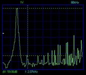
haha!Correct, actually there can be found an optimum for any combination the 3 main parameters of the 1543 DAC:
1. The Rref
2. the Rload
3. The VB
In the 1st picture the combination was 1k38 2k2 and 8,00 Volt
Easy to check with a FFT anlyzer (real one or S/W and your soundcard in the PC) and a test CD which contains a 1kHz 0dB sine wave...... in stead of a fix resitor I used a 25 turn trimmer, just turning till you see the d2 and d3 disapearing almost !! no magic, no rocket sience
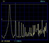
These values were both achieved by measurements as well later with listening tests, which were done blind. I used trimmers for Rref and the VB and found the best position (well best, I prefered this position) I checked the values later on and came up with 1350 Ohm ( !! ) and 8,5 Volt for VB
Just try yourself !!!
by the way, more to come. I still have some ideas which need to be checked
Doede
PS: hope I will be left "out of jail soon"
1. The Rref
2. the Rload
3. The VB
In the 1st picture the combination was 1k38 2k2 and 8,00 Volt
Easy to check with a FFT anlyzer (real one or S/W and your soundcard in the PC) and a test CD which contains a 1kHz 0dB sine wave...... in stead of a fix resitor I used a 25 turn trimmer, just turning till you see the d2 and d3 disapearing almost !! no magic, no rocket sience
These values were both achieved by measurements as well later with listening tests, which were done blind. I used trimmers for Rref and the VB and found the best position (well best, I prefered this position) I checked the values later on and came up with 1350 Ohm ( !! ) and 8,5 Volt for VB
Just try yourself !!!
by the way, more to come. I still have some ideas which need to be checked
Doede
PS: hope I will be left "out of jail soon"
Just another question:
My TDA1543 has significant background noise.
I reported this before but no one could confirm it. I have a pre-amp/DAC combination with 4 different style DAC's inside. The TDA1543 has by far the most background noise, you can hear it from listening position... does anybody else have the same experience?
Regards,
Thijs
That's not right, you make no sense!tschrama said:Hi Fedde,
Damm .. I make no sence today..
 (damn...)
(just kidding!)
tschrama said:
My TDA1543 has significant background noise.
I reported this before but no one could confirm it. I have a pre-amp/DAC combination with 4 different style DAC's inside. The TDA1543 has by far the most background noise, you can hear it from listening position... does anybody else have the same experience?
I share the opinion that the TDA1543 is somewhat noisy. If I really turn up the volume I can hear some noise. But it's not extremely bad and doesn't worry me. It could well be that using a larger I/V increases the SNR...
Fedde
Clairvoyant?
Hi Fedde,
Are you clairvoyant knowing in advance what Doede is going to answer??


fedde said:
Let's answer for Doede:
Doede uses the TDA in passive mode, with 2.2k I/V and 8V supply. In that configuration, the correct Vref setting is essential!!!
Theoretically the DC output level should be at 4.3 V, but Doede says he gets minimal distortion between 3.7 V-4.1V or so. Doede seems to use 1k38, I use 1k26 (4.25V).
Fedde
Hi Fedde,
Are you clairvoyant knowing in advance what Doede is going to answer??
Vref Setting TDA1543
Hi, I just put a 5k pot at Vref and played a bit. Low setting gives a distorted sinewave on the scope, especially at the top. Higher setting is OK. With a little safety margin in the setting the pot measured 3k2.
So Philips might be right using 3k3 in there players. This is with +5V supply and active (opamp) IV-conversion.
Re: Resistor at Vref
I took Doede off moderation, so Fedde doesn't have to predict anymore what Doede meant to say
Elso Kwak said:
After some time your posts are displayed immediately. Newcomers are first subjected to some kind of "filtering", taking some time in the process.....
I took Doede off moderation, so Fedde doesn't have to predict anymore what Doede meant to say
I/V stage
Hallo!
The schematic below derives directly from the Passlabs D1
I build it balanced and implemented successfully into a sony CD player . In that case the Dacs were looking for a virtual ground.
Now , I'm waiting for parts (TDA 1543, receiver etc) and I have not try it or simulate it .
I wonder if it will work with TDA 1543.
rbroer said:Stefanobilliani,
Sure it can work, just change the resistors so, that the gate voltage on Q1 is 2~3V higher compared to the one with virtual ground. This will lift-up the source voltage on Q1, hence the DAC output voltage.
Thanks for the reply rbroer,
what about a constant current source (better PSRR), and at what current? After searchin' around in the thread and projects seems that the preferred current for the TDA1543 is around 7-8 mA for I/V ; can anyone confirm this?
_ _ _ _ _ _ _ _ _ _ _ _ _ _ _ _ _ _ _ _ _ _ _ _ _ _ _ _ _ _ _ _ _ _
Already build 3 massive power supplies , the input receiver...The TDA still not arrived
_ _ _ _ _ _ _ _ _ _ _ _ _ _ _ _ _ _ _ _ _ _ _ _ _ _ _ _ _ _ _ _ _ _
I take the occasion for a question that is pretty interesting for the thread:
the absolute output phase:
I noticed in different projects around the internet that just one case does an exception regarding the pins in the differential input receiver from the SPDIF. The pins are 9 and 10 of the CS8412.
Almost all projects sets the pin 10 (after the cap) at ground , and the pin 9 (after the cap) at the signal.
The TNT-audio CONVERTUS does the opposite: pin 9 at ground and pin 10 at signal.
Does this help to restore the absolute phase at the output of the DAC, since I read at the NONOZ2 DAC page that the TDA1543 inverts the phase?
Thanks
- Status
- This old topic is closed. If you want to reopen this topic, contact a moderator using the "Report Post" button.
- Home
- Source & Line
- Digital Source
- Simple ACTIVE I/V for TDA1543